© 2006 Schneider Electric All Rights Reserved
63230-500-224A1 PowerLogic
®
Series 800 Power Meter
6/2006 Chapter 4—Wiring
EN–33
ENGLISH
Switching of inductive devices such as relay coils and motors results
in high voltage transients from back electromotive force (EMF). To
monitor this type of circuit, use an isolated power supply, such as the
24 Vdc power supply included with the PM8M26, and an auxiliary
contact on the circuit breaker or switch.
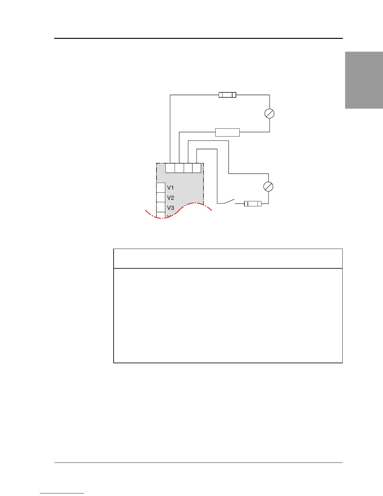
Figure 4 – 16: Standard Input/Output Wiring
8
9
10
11
YC
PM800
K
1
S
1
Load
≤ 100 mA
~
=
≤ 100 mA
Power Source
3 - 250 Vdc
6 - 220 Vac
Power Source
24 - 125 Vdc / Vac
Status Switch or
Auxiliary Contact
Digital Output / Pulse Output
KY is a solid state pulse output
rated for 250 VDC max. or
220 Vac max.
Maximum load current is 100 mA
at 25°C. Derate 0.56 mA per °C
above 25°C.
Digital Input / Status Input / Pulse Input
C1 is the common or voltage reference.
S1 is
the status input signal.
Overcurrent Protective Device
(not supplied)
~
=
NOTE: The overcurrent protective device
must be rated for the short circuit current
at the connection point.
CAUTION
VOLTAGE TRANSIENTS OVER 500 V CAN DAMAGE DIGITAL
INPUTS
• Do not use digital inputs to directly monitor circuits with highly
inductive loads.
• Use auxiliary contacts and isolated power supply when
monitoring inductive loads.
Failure to follow this instruction will result in equipment
damage.