Appendix I RS485 Communication Protocol
I-1.Introduction
PI130 series inverter provides RS232/RS485 communication interface, uses
international standard MODBUS communication protocol for the master-slave
communication. User can use PC/PLC to control the host computer etc so as to achieve
the centralized control (setting control command operating frequency of the inverter,
modifying the relevant function code parameters, monitoring the inverter's operating
status and fault message) to meet specific application requirements .
I-2.Details
1. Protocol content
This serial communication protocol defines the transmission information and use
format in the series communication Including: master polling (or broadcast) format;
master encoding method, and contents including: function code of action, transferring
data and error checking. The response of slave also adopts the same structure, and
contents including: action confirmation, returning the data and error checking etc. If
slave takes place the error while it is receiving information or cannot finish the action
demanded by master, it will send one fault signal to master as a response.
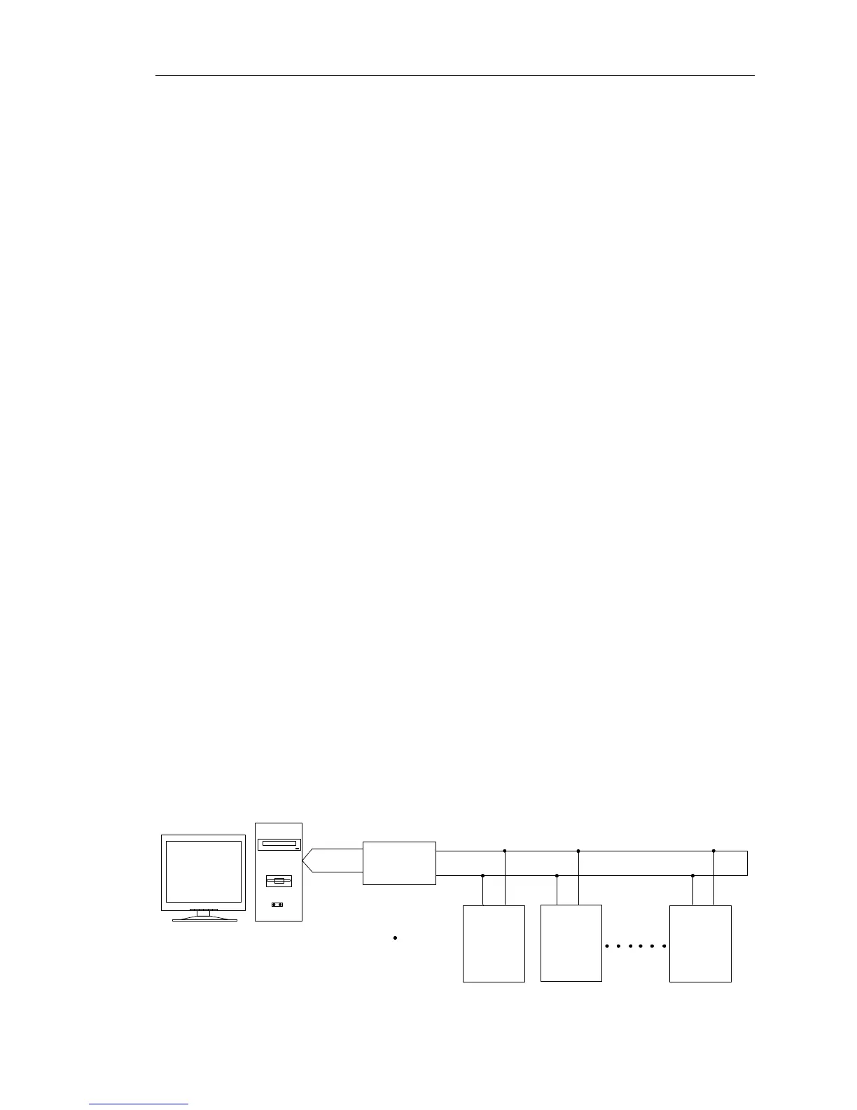
2. Application Method
The inverter will be connected into a “Single-master Multi-slave” PC/PLC control
network with RS232/RS485 bus.
3. Bus structure
(1) Interface mode: RS232/RS485 hardware interface
(2) Transmission mode
Asynchronous series and half-duplex transmission mode. For master and
slave,only one of them can send the data and the other only receives the data at the same
time. In the series asynchronous communication, the data is sent out frame by frame in
the form of message
(3) Topological structure
Single-master and multi-slave system. The setting range of slave address is 1 to
247,and 0 refers to broadcast communication address. The address of slave for network
must be exclusive. As shown below:

 Loading...
