Appendix I RS485 Communication Protocol
111
will be the address field of a new message. Similarly, if a new message begins earlier
than the interval of 3.5 characters following a previous message, the receiving device
will consider it as a continuation of the previous message. This will result in an error,
because the value in the final CRC field is not right.
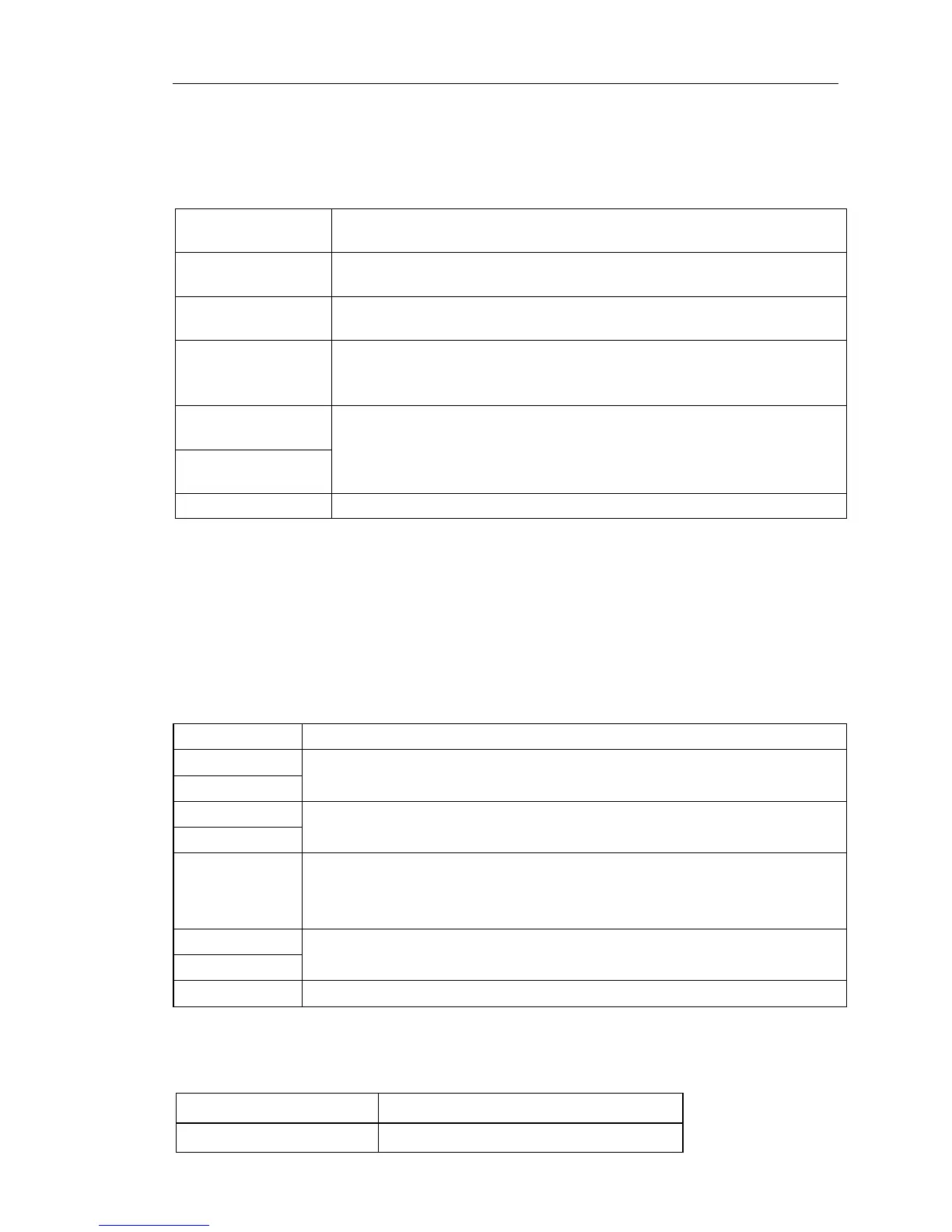
RTU frame format:
T1-T2-T3-T4 (transmission time of 3.5-byte)
Address: 0 to 247 (decimal) (0 is the broadcast address)
03H: read slave parameters;
06H: write slave parameters
Data field
DATA (N-1) …
DATA (0)
2*N bytes of data, the part is the main contents of
communications, but also the data exchange core during
communicating.
Detection value: CRC checksum (16BIT)
T1-T2-T3-T4 (transmission time of 3.5-byte)
(2) In ASCII mode, each byte format is as follows:
In ASCII mode, the frame header is ":" ("0x3A"), the default frame tail is "CRLF"
("0x0D" "0x0A") . In ASCII mode, in addition to header and trailer, the rest of all data
bytes are sent in ASCII code, firstly sent the high 4 bytes, and then send the low 4 bytes.
In ASCII mode, the length of data is eight bytes. For 'A' to 'F', the uppercase ASCII code
is adopted. At this point the data adopts LRC parity, the parity covers slave's address
and data. The sum of parity is equal to the complement of the character sum (discard the
carry bit) of all data to be checked.
ASCII frame standard structure:
Address :8-bit address consists of 2 ASCII codes
Function code :8-bit address consists of 2 ASCII codes
Data Content: nx8-bit data consists of 2n combinations of ASCII
code
n <= 16, maximum 32 ASCII codes
LRC check code: 8-bit check code consists of 2 ASCII codes
Terminator: END Hi = CR (0x0D), END Lo = LF (0x0A)
CMD (Command) and DATA (Data word description) command code: 03H, read N
words (Word) (up to 16 words can be read), such as: the starting address 0001 of
inverter with slave address 01, which continuously read 2 consecutive messages of RTU
master command .

 Loading...
