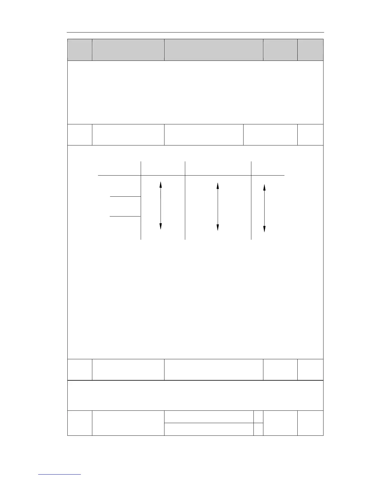
Acceleration and deceleration time schematic that the set frequency is less than
the maximum frequency.
PI130 series inverter has two groups of deceleration time.
First group: F0.05, F0.06; second group: F7.03, F7.04
Acceleration and deceleration time can be selected by using the multi-function input
terminals (F1 group) . The fault value of acceleration and deceleration time is the first
group.
Carrier frequency pair impact diagram
The advantage of high carrier frequency: there are more ideal current waveform, less
current harmonics and less motor noise.
The disadvantage of high carrier frequency: switching loss increases, the inverter
temperature increases, the inverter output is affected, the inverter derates under high
carrier frequency; the leakage current of the inverter increases, the electromagnetic
interference on external increases.
The low carrier frequency has contrary the case described above, the too low carrier
frequency will cause the instability of low frequency operation, the torque reduction
even oscillation.
The inverter has been set reasonably before leaving factory. Under normal
circumstances, user does not need change the parameters.
If the frequency that user uses is more than the default carrier frequency, the derating
is required, derating 20%. each increasing of 1K carrier frequency
Maximum output frequency is used to set the maximum output frequency of inverter.
User shall note that it is the basis of frequency setting, as well as the basis for the
speed of acceleration and deceleration.

 Loading...
