137
3. 3.0mm hex driver or hex L wrench
4. 2.5 mm hex driver or hex L wrench
5. 2.0mm hex driver or hex L wrench
6. Fine point tweezers
7. .06 in flat blade screwdriver
Spare Parts Required:
1. J2 Motor Assembly PN PF02-MA-00011 or J2 Timing Belt PN PF00-MC-X0005.
2. 2 1/8th by 8 in tie wraps
3. Loctite 243
The J2 Motor Assembly is comprised of the J2 motor, connectors, and a timing belt pulley.
The user must:
1. Unbolt the robot from its mounting surface and set it vertically on the floor or a low surface.
2. Move the robot arm to about 2 inches below the top of the Z Column travel.
3. Turn off the robot power and remove the AC power cord.
4. Remove the Top Plate of the robot by removing the 4 M5 socket head screws from the top plate
of the robot that attach the top plate to the Z column.
5. Remove the Front Cover by lifting it out horizontally.
6. Remove the Z carriage inner cover by removing 5 M3 X 10 FHCS.
7. Remove the Light Bar by removing 3 M3 X 8 SHCS and unplugging the connector from the J2
Motor Interface PCA.
8. Remove the tie wrap securing the harness loop to the Z carriage.
9. Remove the M2 and E2 Flat Ribbon Cables from the J2 motor interface board. The E2 connector
Cam lid must be VERY gently pried open with a .06 in flat bladed screwdriver.
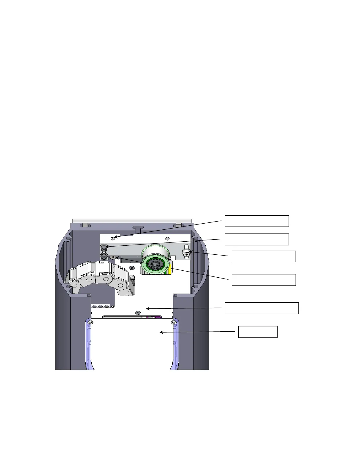
M5 Set Screw
M4 Lockin
Screws
M5 Shoulder Screw
M5 Shoulder Screw
Z Carria
e Inner Cover
Li
ht Bar