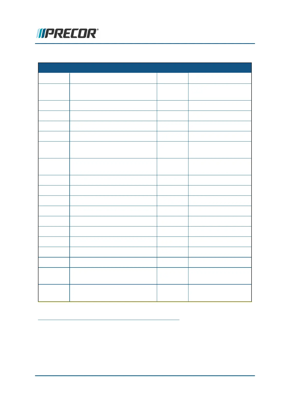
MC connector pin definitions
CONN
1
ID
NAME PIN Description
INPUT MC AC
2
INPUT PWR 1 EARTH GROUND
2 AC LINE 1- LINE AC
LINE
3 AC LINE 2- NEUTRAL
MOTOR DRIVE MOTOR AC PWR OUT 1 NC
2 NC
3 NC
4 BLACK MOTOR PHASE
B
5 WHITE MOTOR PHASE
C
6 RED MOTOR PHASE A
COMM CONSOLE INTERFACE CABLE 1 DIGITAL GROUND
2 +8 VDC
3 TCD DATA OUTPUT
4 DIGITAL GROUND
5 +8 VDC
6 RXD DATA INPUT
7 DIGITAL GROUND
8 E-STOP
3
DBR
4
(1)
DYNAMIC BRAKE RESISTOR
SENSE
1 THERMAL RESISTOR
SENSE
2 THERMAL RESISTOR
SENSE
1
connector
2
Alternating Current: electric current which periodically reverses direction between positive
and negative polarity.
3
Emergency Stop: Safety clip and lanyard attached to the stop switch to immediately turn
off power bringing the treadmill to a stop.
4
treadmill dynamic break resistor.
Contact Precor Customer Support at support@precor.com or 800.786.8404 with
any questions.
Page 111
6 Replacement Procedures
Motor Controller (MC) Replacement