© Precor Incorporated, Unauthorized Reproduction and Distribution Prohibited by Law Page 49
NOTE: All resistance measurements must be performed with power
removed from the treadmill. Performing the resistance measurements
with voltage applied may damage your multi-meter.
5 Set the treadmill’s on/off switch to the off position. Disconnect
the drive motor connector from the OUTPUT connector on the power
control module. With an ohmmeter, measure between terminals 4 (red)
& 5 (white), 4 (red) & 6 (black) and 5 (white) & 6 (black) of the
drive motor connector. Each reading should be approximately 2.5 W
(Ohms). If any of the readings are significantly high or open,
replace the drive motor.
6 If the ohm readings are correct, inspect the female terminals of the
drive motor connector. Verify that they are not spread beyond the
point of making good connection with the male pins on the OUTPUT
connector on the power control module. If proper connection is not
being achieved, the connector CAN BE repaired (using the appropriate
crimper and connector ends) as a preferable solution to replacing a
costly drive motor.
7 If you have performed all of the procedures above and have been
unable to correct the problem, call Precor customer support.
Note: All resistance measurements must be performed with power
removed from the treadmill. Performing resistance measurements with
voltage applied may damage your ohmmeter.
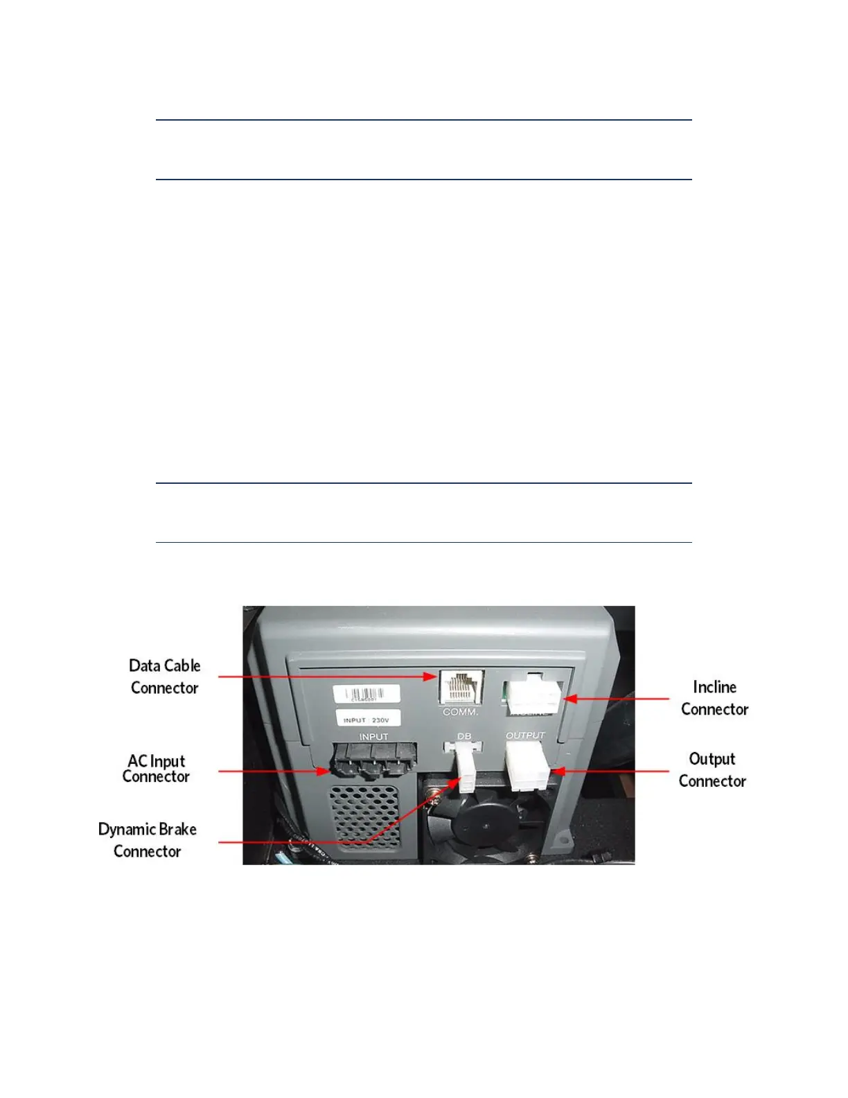
Figure 11: Lower Control Module