© Precor Incorporated, Unauthorized Reproduction and Distribution Prohibited by Law Page 86
9 Set the input module in its mounting position with the side with two
terminals facing the circuit breaker. Replace the hardware that
fastens the module to the input panel.
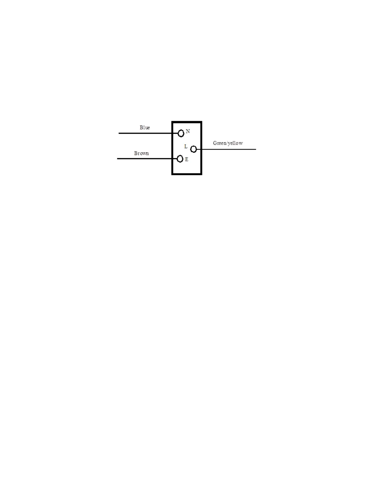
10 Connect the blue wire removed in step 7 to terminal N, the brown wire
to terminal L and the green/yellow wire to terminal E of the input
module.
Figure 27: Input Module Wiring
11 Insert the AC line cord firmly into the input module. Set the AC line
cord clamp in its mounting position and fasten it with the hardware
removed in step 5.
12 Set the input panel in its mounting position and fasten it with the
hardware removed in step 3.
13 Check treadmill operation per, Checking Treadmill Operation (see "Section 4 -
Operation Verification" on page 9).