Start Here MVI56E-MCM ♦ ControlLogix Platform
User Manual Modbus Communication Module
Page 12 of 209 ProSoft Technology, Inc.
1.3 Package Contents
The following components are included with your MVI56E-MCM module, and are
all required for installation and configuration.
Important: Before beginning the installation, please verify that all of the following items are
present.
Modbus Communication Module
Cable #14, RJ45 to
DB9 Male Adapter
cable
For DB9 Connection to Module’s
Application Serial Port
Two Adapters, DB9 Female to Screw
Terminal. For RS422 or RS485
Connections to Port 1 and 2 of the Module
If any of these components are missing, please contact ProSoft Technology
Support for replacement parts.
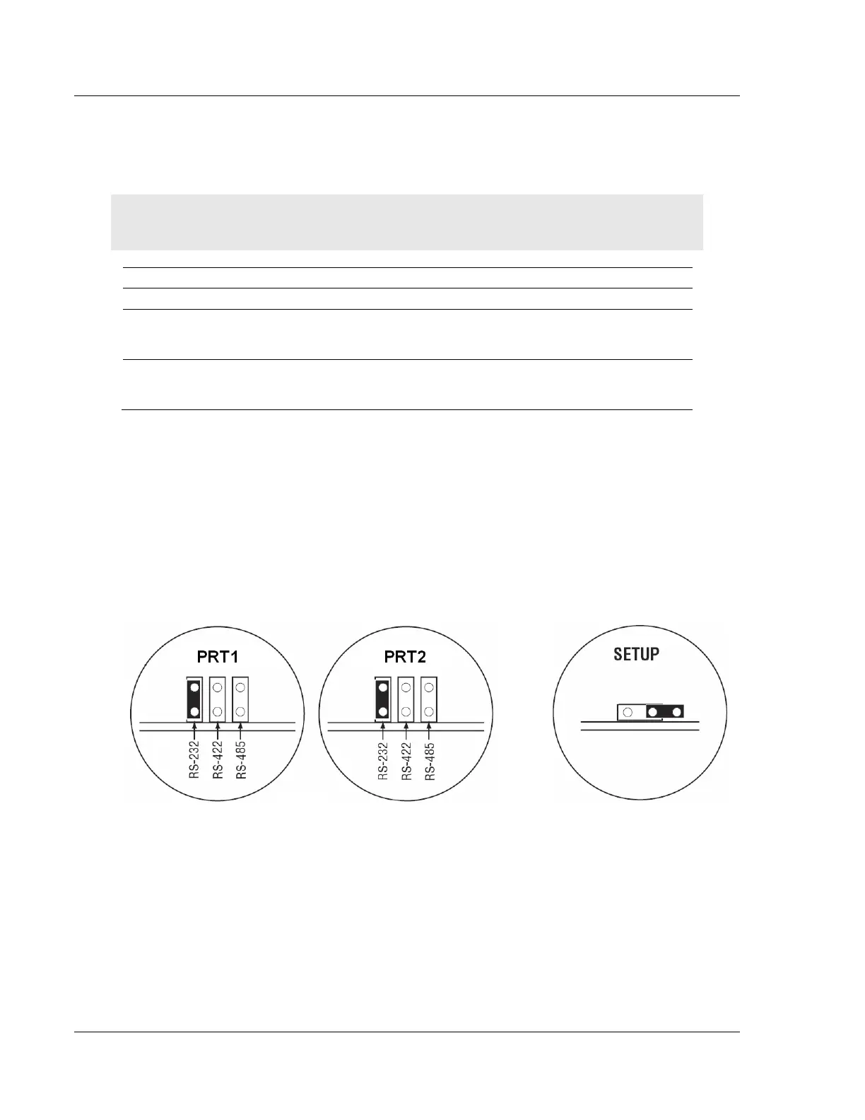
1.4 Setting Jumpers
There are three jumpers located at the bottom of the module. The first two
jumpers (P1 and P2) set the serial communication mode: RS-232, RS-422 or RS-
485.
The following illustration shows the MVI56E-MCM jumper configuration, with the
Setup Jumper OFF.
The Setup Jumper acts as "write protection" for the module’s firmware. In "write
protected" mode, the Setup pins are not connected, and the module’s firmware
cannot be overwritten. The module is shipped with the Setup jumper OFF. Do not
jumper the Setup pins together unless you are directed to do so by ProSoft
Technical Support (or you want to update the module firmware).
The following illustration shows the jumper configuration with the Setup Jumper
OFF.
 Loading...

