Start Here MVI56E-MCM ♦ ControlLogix Platform
User Manual Modbus Communication Module
Page 28 of 209 ProSoft Technology, Inc.
1.6.5 Adjust the Input and Output Array Sizes (Optional)
The module internal database is divided into two user-configurable areas:
Read Data
Write Data.
The Read Data area is moved from the module to the processor, while the Write
Data area is moved from the processor to the module. You can configure the
start register and size of each area. The size of each area you configure must
match the Add-On Instruction controller tag array sizes for the READDATA and
WRITEDATA arrays.
The MVI56E-MCM sample program is configured for 600 registers of READDATA
and 600 registers of WRITEDATA, which is sufficient for most application. This
topic describes how to configure user data for applications requiring more than
600 registers of ReadData and WriteData. In this example, we will expand both
the Read and Write Data sizes to 1000.
Important: Because the module pages data in blocks of 200 registers at a time, you must
configure your user data in multiples of 200 registers.
Caution: When you change the array size, RSLogix may reset the MCM tag values to zero. To
avoid data loss, be sure to save your settings before continuing.
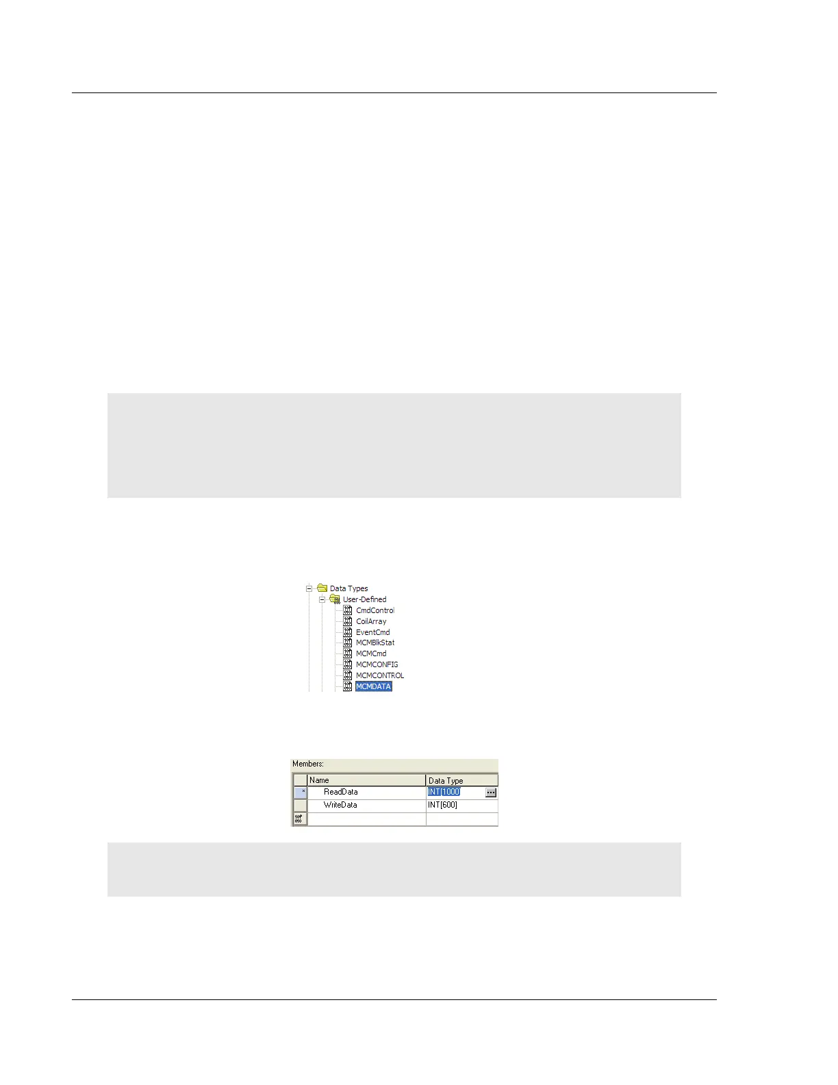
1 In the CONTROLLER ORGANIZATION window, expand the DATA TYPES and
USER-DEFINED folders, and then double-click MCMDATA. This action opens
an edit window for the MCMDATA data type.
2 In the edit window, change the value of the READDATA array from INT[600] to
INT[1000] as shown, and then click APPLY.
Note: If RSLogix resets your data values, refer to the backup copy of your program to re-enter your
configuration parameters.
3 Next, navigate to CONTROLLER TAGS and double click to open an edit
window. Click the MONITOR TAGS tab at the bottom of the edit window.
 Loading...

