Configuration as a Modbus Master MVI56E-MCM ♦ ControlLogix Platform
User Manual Modbus Communication Module
Page 36 of 209 ProSoft Technology, Inc.
2.2 ModDef Settings
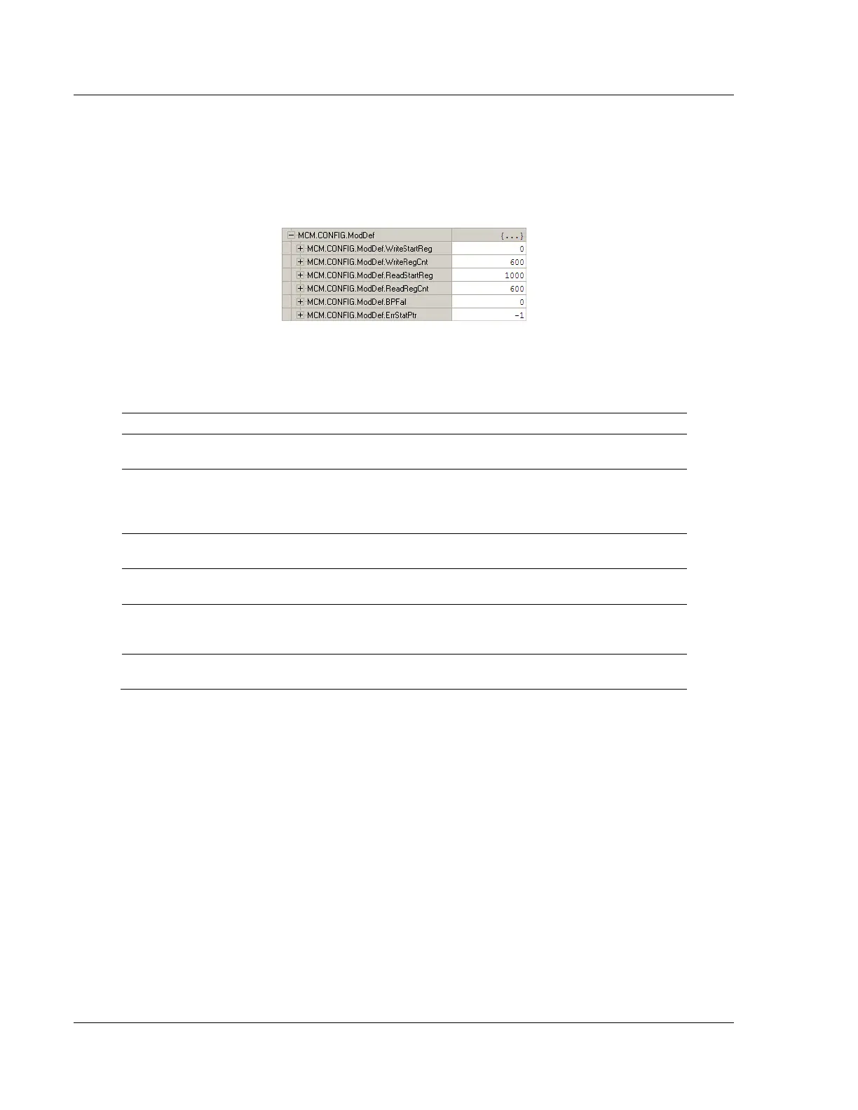
The MCM.CONFIG.MODDEF tag defines the 10,000 data registers to use for read
and write data within the MVI56E-MCM module. You will use these data read and
write locations in the IntAddress tag within each Master Command Configuration
(page 39). The following illustration shows the values from the sample program.
The WRITESTARTREG tag determines the starting register location for the
WRITEDATA[0 to 599] array. The WRITEREGCNT tag determines how many of the
10,000 registers to use to send data to the module. The sample ladder file uses
600 registers for write data, labeled MCM.WRITEDATA[0 to 599].
Specifies where in the 10,000 register module memory to place data
sent from the WriteData tags in the ControlLogix processor.
Specifies how many registers of data the MVI56E-MCM module will
request from the ControlLogix processor. Because the module pages
data in blocks of 200 words, this number must be evenly divisible by
200.
Specifies which registers in the module’s read data area to send to the
ReadData tags in the ControlLogix processor.
Sets how many registers of data the MVI56E-MCM module will send to
the ControlLogix processor. This value should also be a multiple of 200.
Sets the consecutive number of backplane failures that will cause the
module to stop communications on the Modbus network. Typically used
when the module is configured as a Slave.
Also used mainly when the module is configured as a Slave. This
parameter places the STATUS data into the database of the module.
 Loading...

