MVI56E-MCM ♦ ControlLogix Platform Reference
Modbus Communication Module User Manual
ProSoft Technology, Inc. Page 141 of 209
6.2.5 Data Flow Between MVI56E-MCM Module and ControlLogix
Processor
The following topics describe the flow of data between the ControlLogix
processor, MVI56E-MCM module, and nodes on the Modbus network. Each port
on the module can be configured to emulate a Modbus Master device or a
Modbus Slave device, independently from the configuration of the other port.
Only the module database is shared between ports. The sections below discuss
the operation of each mode.
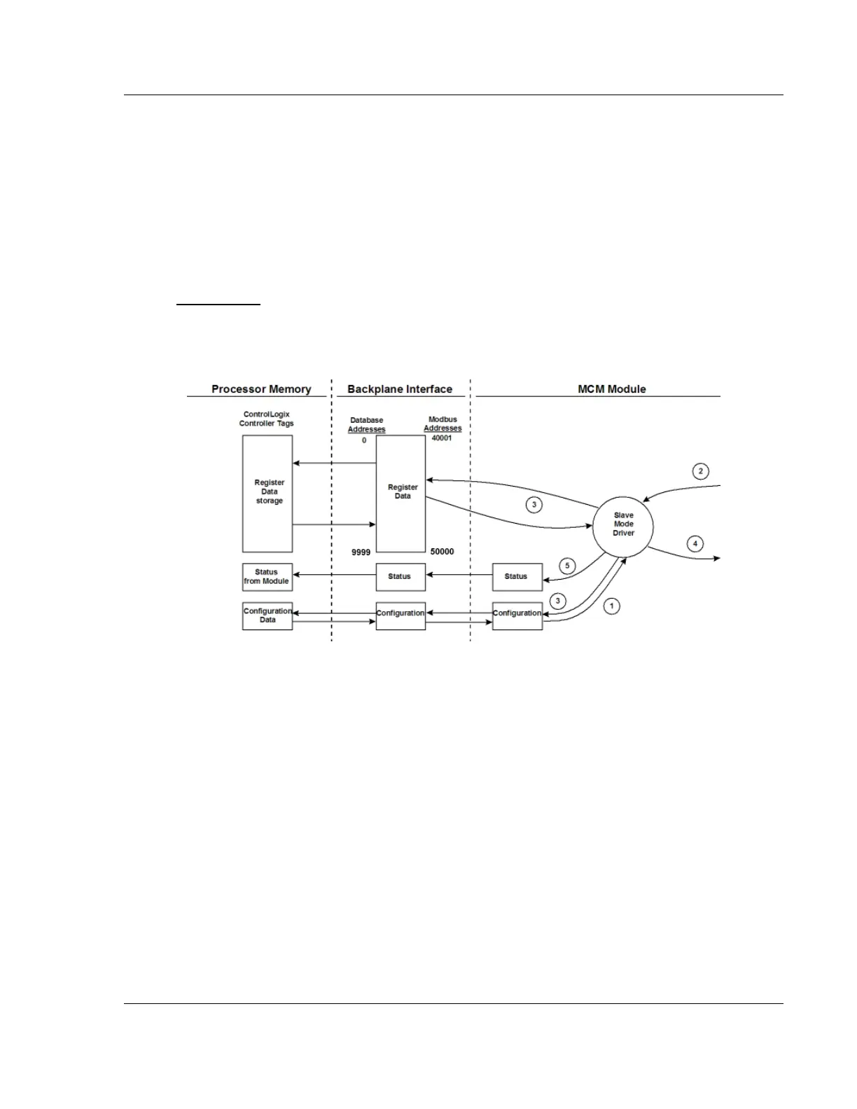
Slave Driver
The Slave Driver Mode allows the module to respond to data read and write
commands issued by a Master on the Modbus network. The following illustration
describes the flow of data to and from the module.
1 The Modbus Slave Port driver receives the configuration information from the
ControlLogix processor. This information configures the serial port and
defines the Slave node characteristics. Additionally, the configuration
information contains data that can be used to offset data in the database to
addresses requested in messages received from Master units.
2 A Host device, such as a Modicon PLC or an HMI application, issues a read
or write command to the module’s node address. The port driver qualifies the
message before accepting it into the module.
3 After the module accepts the command, the data is immediately transferred
to or from the internal database in the module. If the command is a read
command, the data is read from the database and a response message is
built. If the command is a write command, the data is written directly into the
database and a response message is built.
4 After the data processing has been completed in Step 2, the response is
issued to the originating Master node.
5 Counters are available in the Status Block that permit the ladder logic
program to determine the level of activity of the Slave Driver.
 Loading...

