MVI56E-MCM ♦ ControlLogix Platform Reference
Modbus Communication Module User Manual
ProSoft Technology, Inc. Page 125 of 209
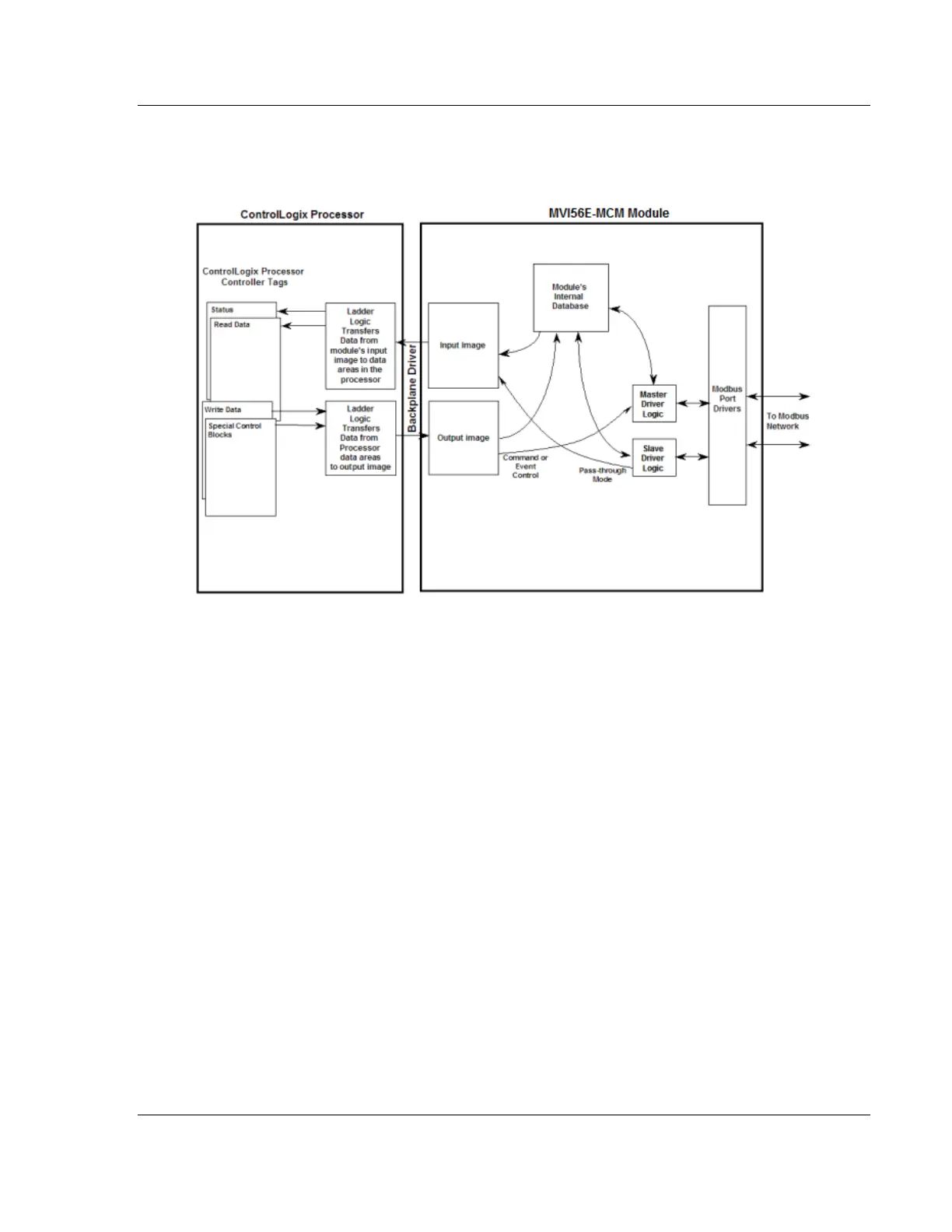
The following illustration shows the data transfer method used to move data
between the ControlLogix processor, the MVI56E-MCM module and the Modbus
Network.
As shown in the illustration above, all data transferred between the module and
the processor over the backplane is through the input and output images. Ladder
logic must be written in the ControlLogix processor to interface the input and
output image data with data defined in the Controller Tags. All data used by the
module is stored in its internal database. This database is defined as a virtual
Modbus data table with addresses from 0 to 15999.
The database is translated into a Modbus data table, according to which a
Modbus command is received or sent. Refer to Modbus Memory Map (page 61)
for more information.
 Loading...

