Verify Communication MVI56E-MCM ♦ ControlLogix Platform
User Manual Modbus Communication Module
Page 72 of 209 ProSoft Technology, Inc.
To be useful in the application, these error codes must be placed within the
MCM.DATA.READDATA array.
Once again, the configuration in the MCM.CONFIG.MODDEF section for
READSTARTREG, and READREGCOUNT determine which of the 10,000 registers
will be presented to the ControlLogix processor and placed in the tag
MCM.DATA.READDATA array.
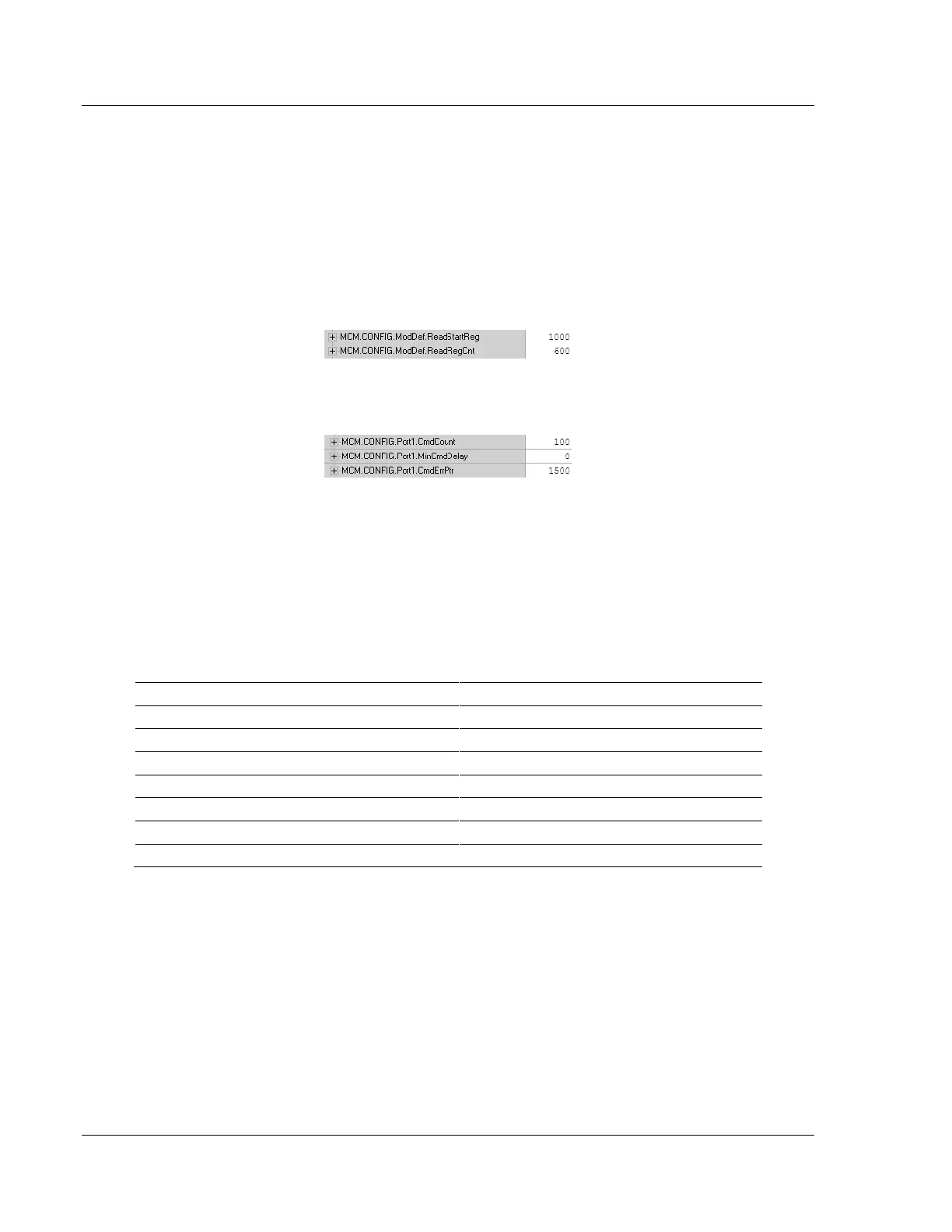
Based on the sample configuration values for READSTARTREG and
READREGCNT, this will be addresses 1000 to 1599 of the module memory. Below
are the sample configuration values.
Based on these values shown above, a good place for the
MCM.CONFIG.PORTX.CMDERRPTR is address 1500, as shown.
With the CMDERRPTR pointer set to address 1500 and the CMDCOUNT set to a
value of 100, this will place your Command Error Data at addresses 1500 to
1599 of the module memory, and because of the before mentioned configuration
of the MCM.CONFIG.MODDEF READSTARTREG and READREGCNT parameters,
the command error data will be placed into the tags MCM.DATA.READDATA[500]
TO [599].
Each command configured in the MCM.CONFIG.PORTX.MASTERCMD will occupy
one register within the READDATA array. Based on the sample configuration
values, the following table is true.
MCM.CONFIG.Port1MasterCmd[0]
MCM.CONFIG.Port1MasterCmd[1]
MCM.CONFIG.Port1MasterCmd[2]
MCM.CONFIG.Port1MasterCmd[3]
MCM.CONFIG.Port1MasterCmd[4]
MCM.CONFIG.Port1MasterCmd[98]
MCM.CONFIG.Port1MasterCmd[99]
 Loading...

