1 2 3 4
ON ECE
SW1
JP6
FLASH
24V ac
10 11
Q80A_8_2017 10
PROTECO S.r.l.
Via Neive, 77 - 12050 Castagnito (CN) ITALY Tel. +39 0173 210111 - Fax +39 0173 210199 info@proteco.net - www.proteco.net
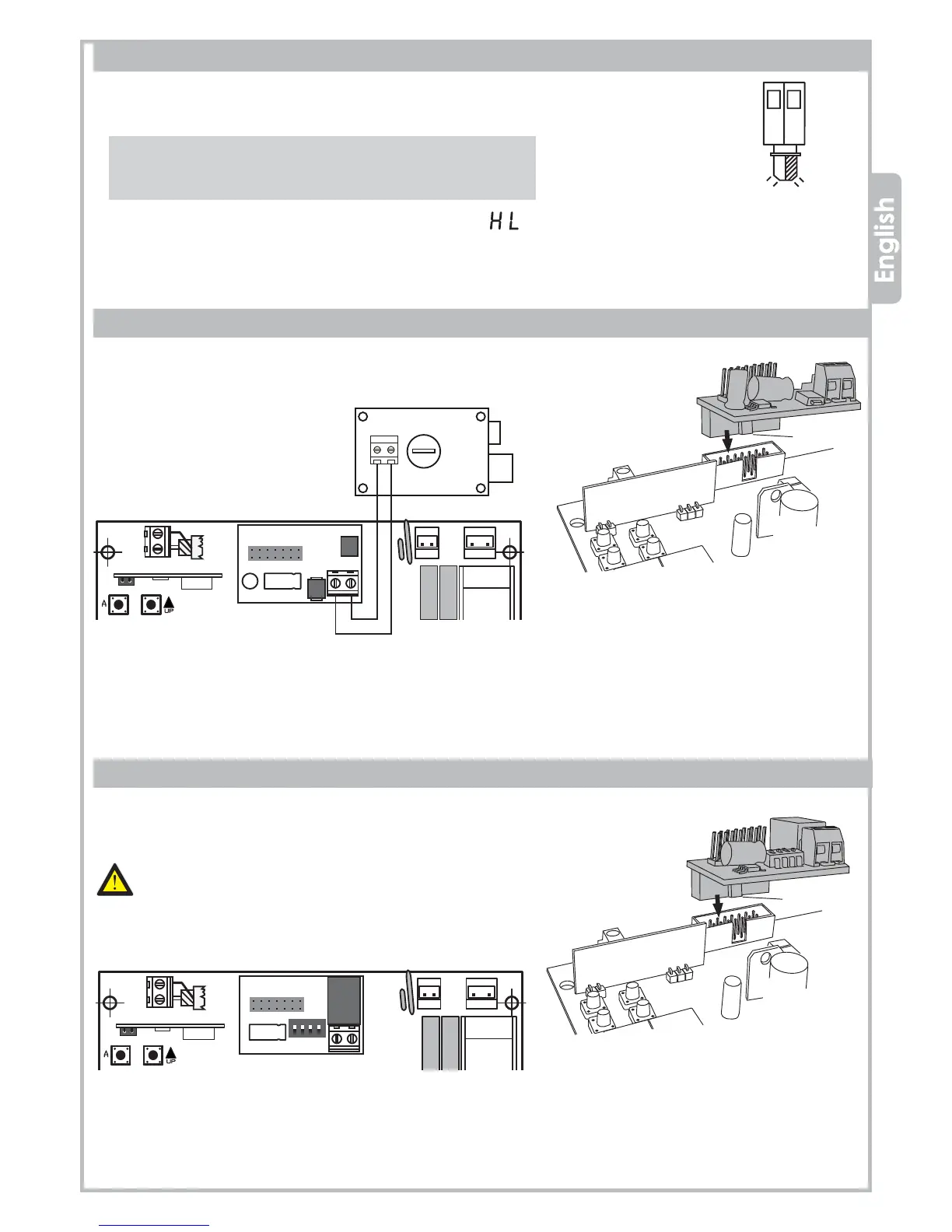
3.9 ELECTRIC-LOCK wiring
Plug the interface module MEL04 (optional) into J5 connector, please
pay attention to the module’s orientation as shown in the picture.
Then wire the electric-lock to the MEL04 terminals.
Electric-lock
12V max 15W
Electric-lock
module
MEL04
Additional
module
MRX01
3.10 AUX/2ND RADIO CHANNEL module
Electric-lock
module
MEL04
Driving
slot
Driving
slot
Plug the additional MRX01 module (optional) into J5 connector,
please pay attention to the module’s orientation as shown in the picture.
Before setting the dip-switches SW1 on the AUX module,
make sure that the control panel is disconnected from any
power supply.
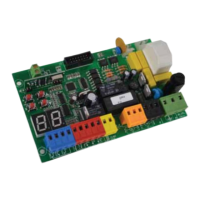
3.8 BLINKER wiring
You can wire a flashing light (20W max) to 10 - 11 terminals on JP6
terminal block.
The flashing light will behave as follows:
• QUICK flashing → the gate is OPENING
• SLOW flashing → the gate is CLOSING
• STILL light on → the gate is in PAUSE TIME before the
automatic closing
Note: You can select the kind of flashing light with
parameter in the FUNCTIONS menu.