13
1. CO
2
module interface 2. SpO
2
module interface
3. LVDS interface 4. Power cord clamp
5. Battery installation position 6. Ground pole
7. System switch 8. No obstruct silk-screen
9. Power input silk-screen 10. O
2
inlet silk-screen(0.28~0.6MPa)
11. O
2
inlet 12. Air inlet
13. Air inlet silk-screen(0.28~0.6MPa)
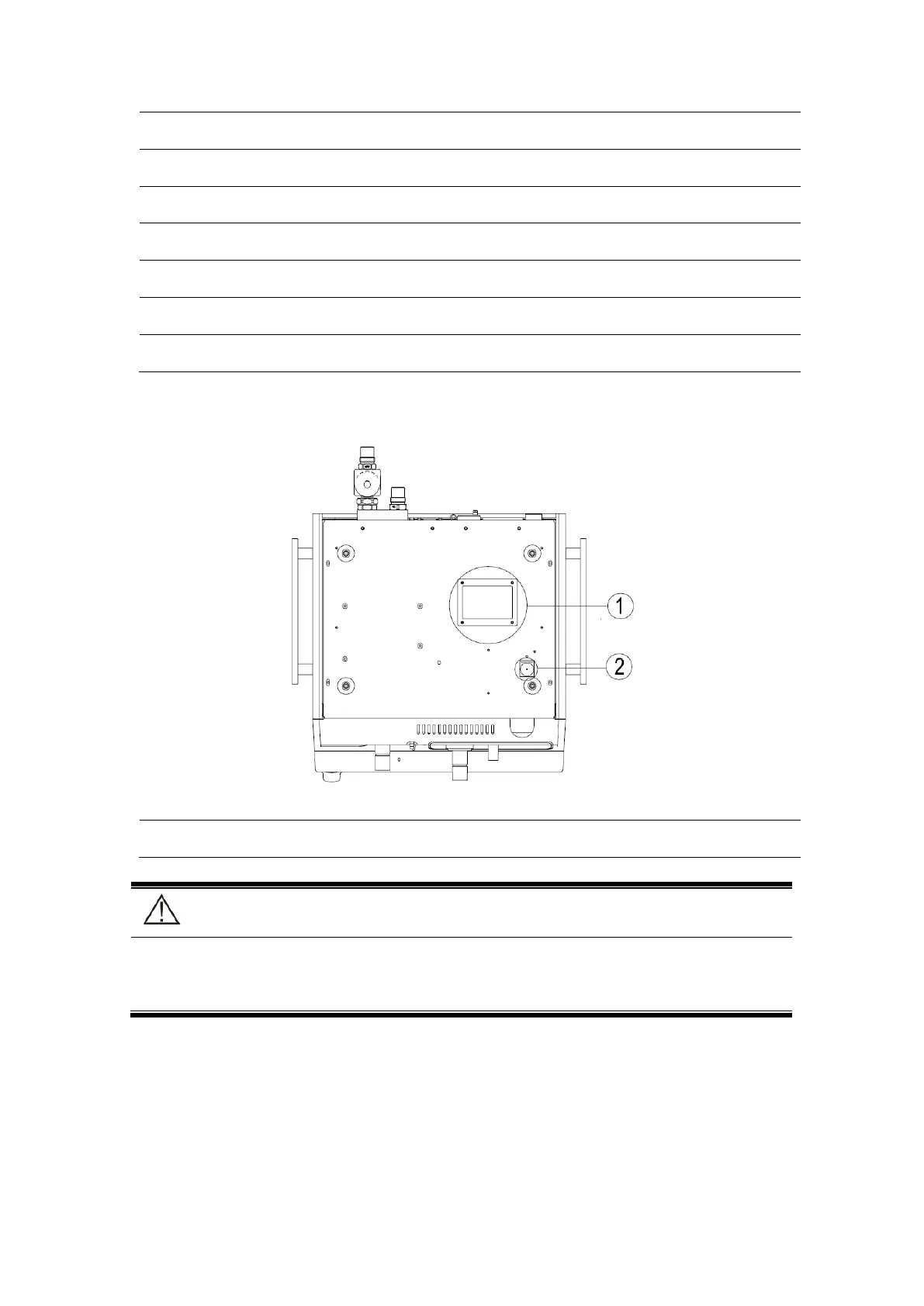
2.2.6 Ventilator bottom view
Figure 2-6 Ventilator bottom view
1. Emergency AIR suction port 2. Exhaust port
Caution:
Do not block the emergency AIR suction port and exhaust port located on the bottom
of the equipment shown as above figure.
2.3 Power supply
1. Power supply specification: Input voltage:100~240V, Frequency: 50/60Hz; Current
Input: 1.5A (Max.).
2. Fuse gear specification: T2AL/250V.
 Loading...