LTE-A Module Series
EM120R-GL&EM160R-GL Hardware Design
EM120R-GL&EM160R-GL_Hardware_Design 35 / 79
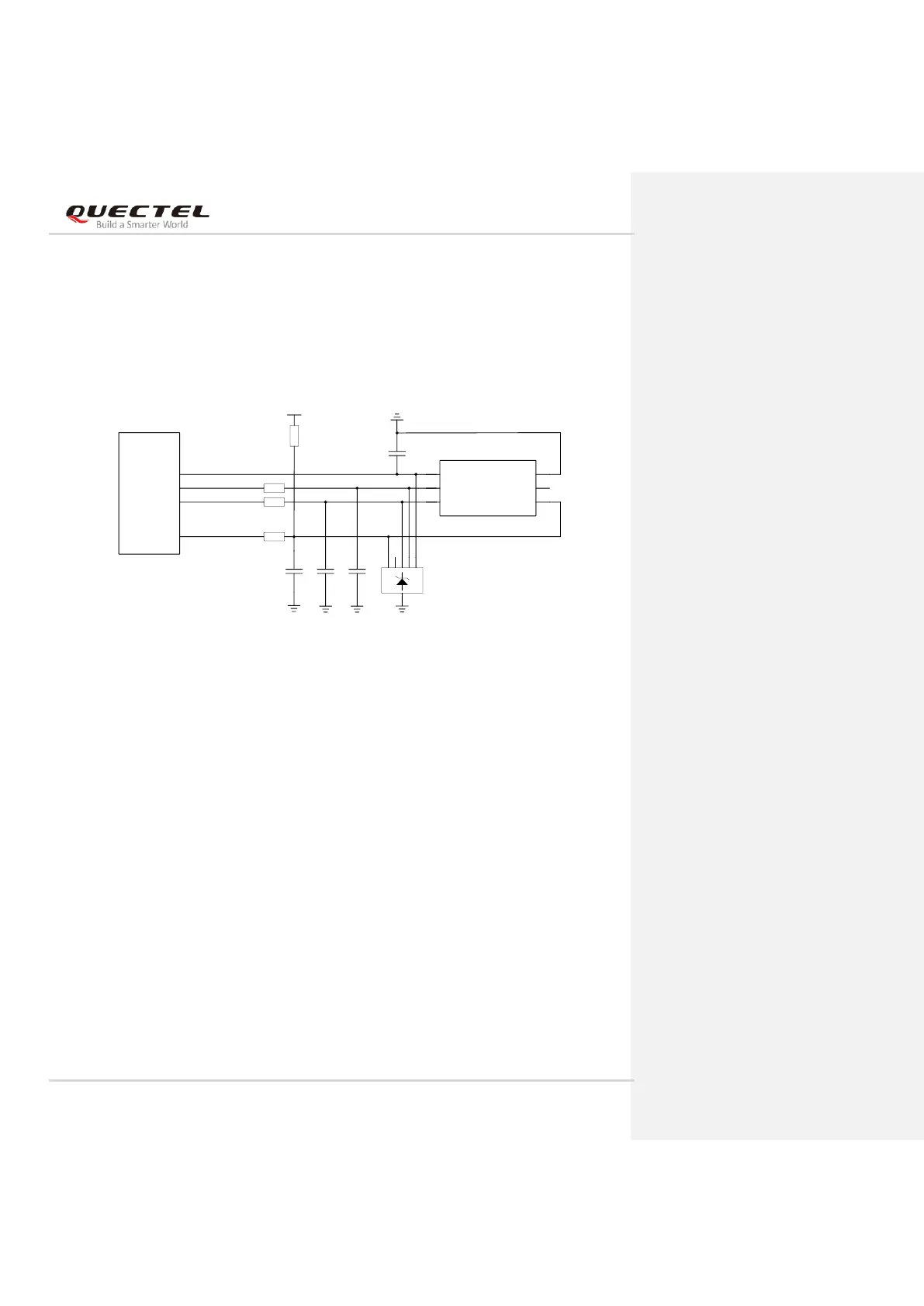
Normally Open (U)SIM Card Connector:
⚫ When the (U)SIM is absent, CD is open to SW and USIM_DET is at low level.
⚫ When the (U)SIM is inserted, CD is short-circuited to SW and USIM_DET is at high level.
If (U)SIM card detection function is not needed, keep USIM_DET unconnected. The following figure
shows a reference circuit for a (U)SIM card interface with a 6-pin (U)SIM card connector.
Figure 19: Reference Circuit of a 6-Pin (U)SIM1 Card Connector
EM120R-GL&EM160R-GL provide two (U)SIM interfaces. (U)SIM1 interface is used for external (U)SIM
card only, and (U)SIM2 interface is used for external (U)SIM card or internal eSIM card.
It should be noted that, when (U)SIM2 interface is used for an external (U)SIM card, the reference circuits
are the same as those of (U)SIM1 interface. When (U)SIM2 interface is used for the internal eSIM card,
pins 40, 42, 44, 46 and 48 of the module must be kept open.