EasyManua.ls Logo

Quectel LTE-A Module Series - Page 35

Quectel LTE-A Module Series
86 pages
Print Icon
To Next Page IconTo Next Page
To Previous Page IconTo Previous Page
Loading...
LTE-A Module Series
EM120R-GL&EM160R-GL Hardware Design
EM120R-GL&EM160R-GL_Hardware_Design 34 / 79
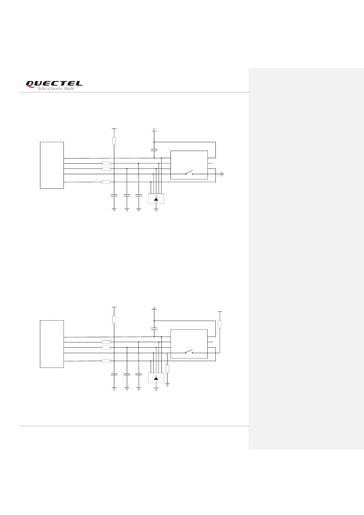
The following figure shows a reference design for a (U)SIM interface with normally closed (U)SIM card
connector.
Module
USIM_VDD
USIM_RST
USIM_CLK
USIM_DATA
USIM_DET
22R
22R
22R
100 nF
(U)SIM Card Connector
GND
GND
33 pF
33 pF 33 pF
VCC
RST
CLK
IO
VPP
GND
GND
USIM_VDD
15K
GND
CD SW
Figure 17: Reference Circuit of Normally Closed (U)SIM1 Card Connector
Normally Closed (U)SIM Card Connector:
When the (U)SIM is absent, CD is short-circuited to SW and USIM_DET is at low level.
When the (U)SIM is inserted, CD is open to SW and USIM_DET is at high level.
The following figure shows a reference design for a (U)SIM interface with normally open (U)SIM card
connector.
Module
USIM_VDD
USIM_RST
USIM_CLK
USIM_DATA
USIM_DET
22R
22R
22R
100 nF
(U)SIM Card Connector
GND
33 pF
33 pF 33 pF
VCC
RST
CLK
IO
VPP
GND
GND
USIM_VDD
15K
GND
CD
1.8 V
4.7K
33K
SW
Figure 18: Reference Circuit of Normally Open (U)SIM1 Card Connector

Table of Contents

Related product manuals