Extended Manual for RF919 v2.1
© 2024 page 18 of 63
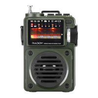
5.6 Switch and socket on the back side of the radio
The RF919 comes with a built-in rod antenna. Alternatively, an external
antenna can be connected to the radio, replacing the internal rod antenna.
5.6.1 External antenna connected to the 3.5mm TRS
An external antenna can be connected to the 3.5mm TRS socket marked
“⚫ EXT.ANT ⚫” at the backside of the radio. As soon as the 3.5mm plug is inserted
into the 3.5mm TRS socket, the internal rod antenna gets disconnected from the
radio. The connections of the TRS socket at the backside of the radio are as
follows:
5.6.2 Automatic mode for MW and SW
Normally the antenna signal is routed by the automatic mode via the following RF
channels
• 10db attenuation
• 20dB attenuation
• HighPassFIlter (HPF) for frequencies above 30 MHz,
• LowPassFilter (LPF) for frequencies below 30 MHz
• LowNoiseAmplifier (LNA1) or
• direct connection
to the LowNoiseAmplifier LNA2.
Notes: More details on the internal building blocks to be found in chapter 20 “Use of
antennas” on page 55.
5.6.3 Manual mode for MW, SW1 and SW2
Alternatively, the antenna signal can be routed via the manual antenna tuner,
tuned by its manual tuning knob [ ] and the manual switch on the backside of
the radio via the SW antenna tuner selection to the very same LowNoiseAmplifier
LNA2.
If used with a suitable external antenna, connected to the socket on the backside
of the RF919, the radio supports a manual antenna tuning function for
MW, SW1 and SW2 using the manual tuning knob [ ] on the right side of the radio.
This can improve the receiving sensitivity to a certain extent if used correctly. But
if the tuning method is not used correct, the receiving performance may be even
worse than if the internal antenna is used.