Extended Manual for RF919 v2.1
© 2024 page 19 of 63
5.6.3.1 Manual MW tuning
When the switch is set to the “MW” position, turn the manual tuning knob [ ] on
the right of the radio and observe the SNR and RSSI readings on the secondary
screen. The higher the values, the better. The best position of the manual tuning
knob can be determined by listening to the clarity of the sound.
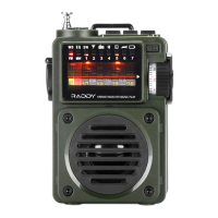
5.6.3.2 Manual SW tuning
When the switch is set to either the “SW1”-position (5…15 MHz) or to the “SW2”-
position (13…30 MHz), press the Antenna select [ ] key to select manual tuning.
The primary screen will display “ “. Now turn the manual tuning
knob [ ] on the right of the radio and observe the SNR and RSSI readings on the
secondary screen. The higher the values, the better. The best position of the
manual tuning knob can be determined by listening to the clarity of the sound.
5.7 Buttons and sockets on the top side of the radio
On the top of the RF919 two more sockets for connection of external
antennas are located.
5.7.1 WT antenna connected to SMA-m socket
The male SMA-socket “ WT ⚫” on top of the radio can be used in combination with
a Walky-talky (WT) antenna suitable for the selected band (either VHF, UHF or AIR
band).
5.7.2 External loop antennas connected to the 3.5mm TRS socket
If you are familiar with creating your own loop antenna for Long Wave (LW),
Medium Wave (MW) and Short Wave (SW), you may do so and connect such to the
3.5mm TRS socket at the top of the radio. The connections are as follows:
Make sure that the LW antenna should have an inductance of 2.2mH. The MW
antenna should have an inductance of 250µH and the SW1 antenna should have
an inductance of 7.5µH (for the frequency range 2.4…8MHz). The SW2 antenna
may be just a ring antenna. The radio has a built-in adaptive tuning function for
LW, MW and SW1, whereas for SW that function is not activated by default.
5.7.3 Switch for activating external loop antennas
To activate an external antenna connected to the 3.5mm TRS socket on the top of
the radio, turn the switch right beside the TRS socket from the default “OFF”-
position to its “ON-ANT”-position.
Notes: Keep in mind that all antenna connectors are sensitive to static electricity and
may easily get damaged if you do not take extreme care on that.