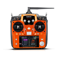
34
Auxiliary channel function (including channel 9-10 controls)(
AUX-CH
GH¿QHVWKHUHODWLRQVKLSEHWZHHQWKHWUDQVPLWWHU
controls and the receiver output for channels 5-10. Also, the
CH9-10 POSI
are used to change the CH9-10 servo direction.
Adjustability:
• channels 5-8 may be assigned to any SWITCH (A-H), LOGIC SWITCH
(Lsw1-Lsw3), slider [VR(D) and VR(E)], or knob [VR(A-C)] (for example,
moving flaps to a switch or slider), but not the primary control sticks (use
programmable mixes to do so, p. 68);
• channel 9-10 may be assigned to any SWITCH (A-H), LOGIC SWITCH
(Lsw1-Lsw3) and the servo direction may be changed.
• multiple channels may be assigned to the same switch, slider or knob;
• channels set to "NULL" are only controlled by mixes. (Ex: utilizing 2 channels
for 2 rudder servos. See mixes, p. 68.)
•If
GYRO SENSE
, GOVERNOR, and
THR-NEEDLE
functions are activated,
AUX-CH
settings of related channels become invalid automatically.
Related channels:
GYRO SENSE
(
ACRO
): ch. 5, 7, or 8: see p. 56.
GYRO SENSE
(
HELI
): ch. 5: see p. 85.
GOVERNOR
(
HELI
): ch. 7, or ch. 7 and 8: see p. 86.
THR-NEEDLE
(
ACRO
HELI
): ch. 8: see p. 50.
Remember that if you assign primary control of a channel to a switch which you later use for other functions (like
GXDOWULSOHUDWHVRUDLUEUDNHVHYHU\WLPH\RXXVHWKDWRWKHUIXQFWLRQ\RXZLOODOVREHPRYLQJWKHDX[LOLDU\FKDQQHO
GOAL of EXAMPLE: STEPS: INPUTS:
$VVLJQÀDSVWRWKHULJKWVOLGHU>VR(E)]
and set channel 7 to
NULL
in preparation
to use it as a smoke system control (the
smoke system being activated later by a
throttle-to-ch.-7 mix).
Open
BASIC
menu, then open
AUX-CH
function.
for 1 second.
(If
ADVANCE
, again.)
C
to
AUX-CH
.
Choose the channel to change. (ex: ch.
6.)
to
Ch 7
.
Change primary control. (ex: to slider.)
to
Vr-E
.
Repeat as needed. (ex: ch. 7 to
NULL
.)
to
Ch 7
. to
NULL
.
Close.
Where next? Programmable mixes: see p. 68.
6HWXSGXDOWULSOHUDWHVDQGH[SRQHQWLDO
D/R
,
EXP
): see p. 30.
Adjust
SUB-TRIM
of auxiliary channel to adjust center SWITCH position:
see p. 36.
Adjust
END POINTs
(sets end points of travel even when using a switch):
see p. 27.
TRAINER
: for training novice pilots with optional trainer cord connecting 2 transmitters. The instructor has several levels of
controllability.
Adjustability:
•
NORM
: When the TRAINER SWITCH is ON, the channel set to this mode can
be controlled by the student. The set channel is controlled according to any
programming set at the student's transmitter.
•
FUNC
: When the TRAINER SWITCH is ON, the channel set to this mode can
be controlled by the student, controlled according to any mixing set at the
instructor's transmitter.