GOAL of EXAMPLE: STEPS: INPUTS:
$GMXVWWKHÀDSVHUYRV
SUB-TRIM
untilits
center exactly matches the aileron
servo's center, as they are to work
WRJHWKHUDVÀDSHURQV
Open
BASIC
menu, then open
SUB-TRIM
.
for 1 second.
(If
ADVANCE
, again.)
C
to
SUB-TRIM
.
Choose the channel to adjust, andadjust
XQWLOVXUIDFHVPDWFK([ÀDS
C
to
FLAP
as needed.
C
to each channel,
Repeat for other channels.
as needed.
Close.
Where next? Adjust trim steps: see p. 35.
Adjust
END POINTs
: see p. 27.
6HWXSGXDOWULSOHUDWHVDQGH[SRQHQWLDO
D/R
,
EXP
): see p. 30.
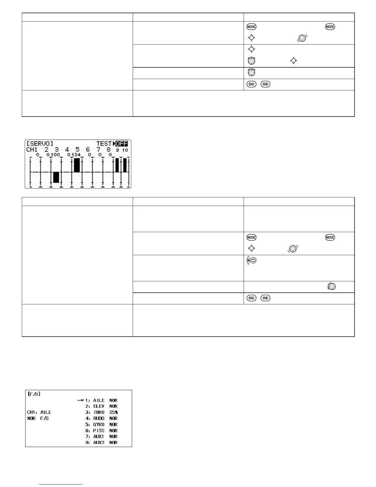
The servo submenu includes two features:
• real-time bar-graph display to demonstrate exactly what commands the
transmitter is sending to the servos. (This can be particularly handy in setting
up models with complicated mixing functions, because the results of each
stick, lever, knob, switch input and delay circuit may be immediately seen.)
VHUYR F\FOH IXQFWLRQ WR KHOS ORFDWH VHUYR SUREOHPV SULRU WR LQÀLJKW IDLOXUHV
(channels 1-8)
GOAL of EXAMPLE: STEPS: INPUTS:
View the result of reassigning channel
6 from VR(A) knob to three-position
SWITCH C.
Cycle the channel 6 servo.
Complete desired programming
function. (Ex: in
AUX-CH
, move ch. 6 to
SWITCH C)
See
AUX-CH
for details. (p. 34.)
Open the
SERVO
function.
for 1 second.
(If
ADVANCE
, again.)
C
to
SERVO
.
Move each control to see exactly how
operating. (Ex: SWITCH C in all
positions)
C to center position.
Note change in position of ch. 6 servo.
Prepare all servos to be cycled and cycle.
Plug in servos. POWER ON.
End cycling and close.
Where next? 6HWXSGXDOWULSOHUDWHVDQGH[SRQHQWLDO
D/R
,
EXP
): see p. 30.
Set up desired programmable mixes: see p. 47.
Set up dual aileron servos: see p. 39.
Set up dual elevator servos: see p. 44.
SERVO
display and cycle submenu: displays radio's output to channels 1-10.
FailSafe (loss of clean signal and low receiver battery) submenu
F/S
): sets responses in case of
loss of signal or low Rx
FailSafe (
F/S
LQVWUXFWVD*UHFHLYHUZKDWWRGRLQWKHHYHQWUDGLRLQWHUIHUHQFHLVUHFHLYHG
Adjustability:
•Each channel may be set independently.
• The
NOR
(normal) setting holds the servo in its last commanded position.
• The
F/S
(FailSafe) function moves each servo to a predetermined position.
• NOTE: the setting of the throttle's
F/S
also applies to the Battery
F/S
(see
below).
(
Battery.