Adjustability:
• Travel: Adjust the amount of elevator, aileron and rudder travel automatically applied.
• Range: -120 to +120 on all 3 channels. Default is
100%
of range of all 3 channels.
• Directions:8SWRVHSDUDWHVQDSVPD\EHVHWXSRQHIRUHDFKRIWKHGLUHFWLRQFKRLFHVXSULJKWGRZQULJKWXSOHIW
GRZQOHIW(DFKVQDSLVIXOO\DGMXVWDEOHUHJDUGLQJWUDYHOVDQGGLUHFWLRQRQHDFKRIWKHFKDQQHOV
Note: for simplicity, the radio refers to snaps that use “UP” or positive elevator as “U” or “UP” snaps. This is more
commonly referred to as a positive or inside snap. “D” or “DOWN” snaps are more commonly referred to as negative or
outside snaps.
•
R/U
= Right positive
R/D
= Right negative
L/U
= Left positive
L/D
= Left negative snap roll
• Assignment of the 2 switches (
DIR-SW1/2
) to change snap directions is fully adjustable and optional. If you wish to have
only one snap, leave the switches as
NULL
. (If assigned,
SW1
XSGRZQ
SW2
OHIWULJKW
• Caution: it is critical that you remember if you assigned switches to select the three additional snaps.
• For example, assign SWITCH A IRU 8' VQDS GLUHFWLRQ DQG WKHQ DOVR DVVLJQ SWITCH A for elevator dual rates.
:KLOHÀ\LQJRQHOHYDWRUORZUDWHSWITCH A DOWN) you pull your snap SWITCH. The model will:
•use the throws set in the snap programming (the low rate elevator has no effect); and
EHDGRZQQHJDWLYHRXWVLGHVQDSQRWDQXSSRVLWLYHLQVLGHVQDS
•Both of these may come as a great surprise and risk crashing if you are unprepared.
• Safety Switch (
SAFE-MOD
): a safety may be set up on your landing gear SWITCH, preventing accidental snap rolls while
the landing gear is down. The safety switch is turned on and off with the landing gear SWITCH.
•
ON
: the safety mechanism is activated when the landing gear SWITCH is in the same position as at the time this
feature is changed to
ON
. Snap rolls will not be commanded even if the snap roll SWITCH is turned on with the
gear SWITCH in this position. When the landing gear SWITCH is moved to the opposite position, snap rolls may
be commanded.
•
OFF
: activates the safety mechanism in the opposite position from the
ON
function.
•
FREE
: the safety mechanism is completely turned off. Snaps can be commanded regardless of the gear SWITCH
POSITION.
Note: The location of the safety switch always follows channel 5. If channel 5 is reassigned to switch C, for
example, switch C is now the safety. If channel 5 is nulled or used as the second aileron servo, the safety function
will not be available.
• Trainer Safety:
SNAP-ROLL
is automatically disabled when the trainer function is activated.
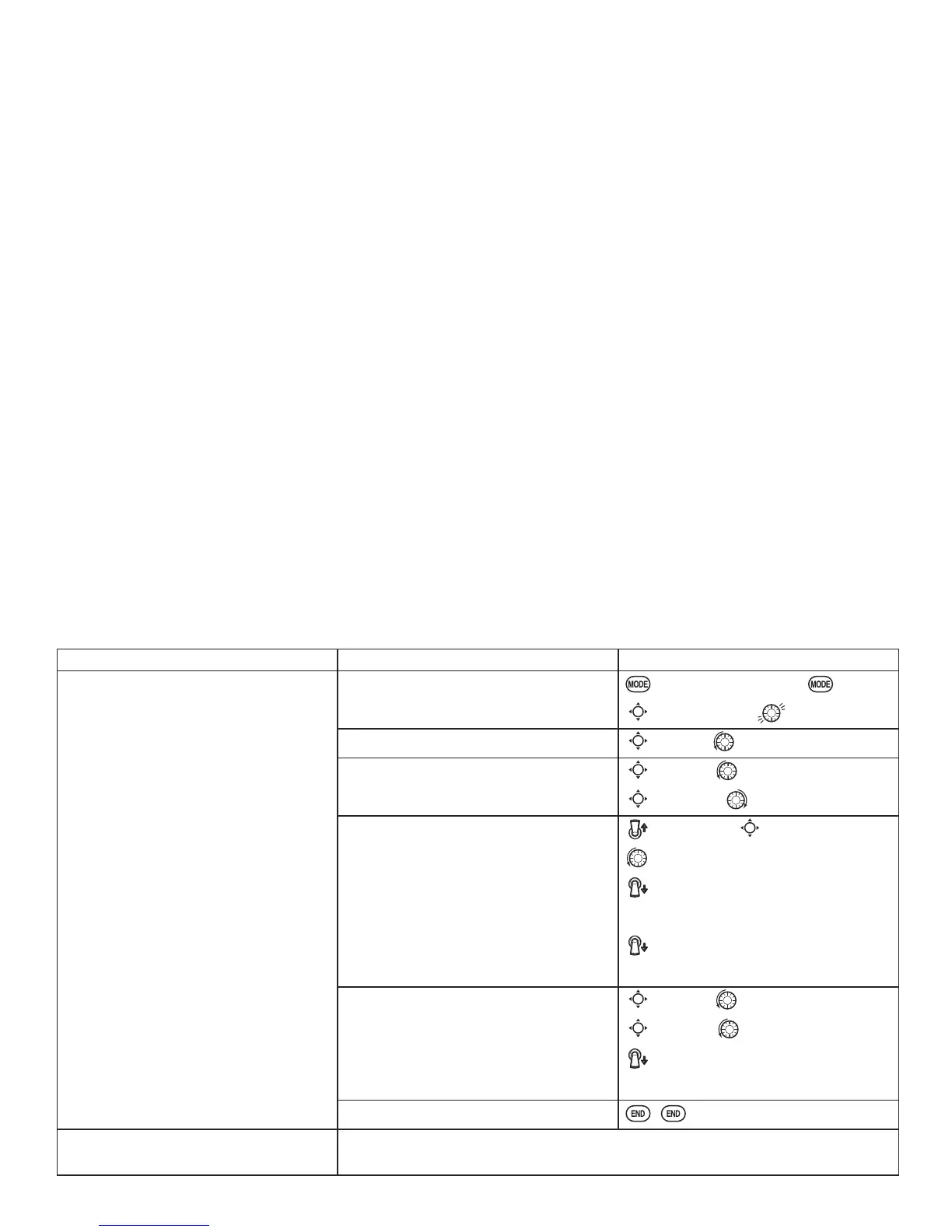
GOAL of EXAMPLE: STEPS: INPUTS:
Activate
SNAP-ROLL
. Adjust
elevatortravel to
55%
, rudder travel to
120%
LQWKHULJKWXSVQDS$FWLYDWH
SAFE-MOD
so snaps can not be performed
when gear is down.
$GMXVWUXGGHUWUDYHOLQWKHOHIWGRZQ
snap to
105%
.
(Note: using negative percents can
change any of the 4 snap directions. For
example, change snap 1 to "down" by
changing the elevator percent to
-100%
.)
Open the
SNAP-ROLL
function.
for 1 second.
(If
BASIC
, again.)
C
to
SNAP-ROLL
.
Activate the function.
C
to
MIX
. to
OFF
or
ON
.
Adjust the travels as needed. (Ex:
elevator to
55%
, rudder to
120%
.)
C
to
ELEV
. to
55%
.
C
to
RUDD
. to
120%
.
Optional: Activate
SAFE-MOD
. [Ex: ON
when SWITCH E (AT10) or G (AT10)
is down, meaning snap function is
deactivated when that switch is in the
down position.]
E or G up.
C
to
SAFE-MODE
to
ON
.
snap switch.
Notice
MIX
reading is still
OFF
.
E or G down.
Notice
MIX
reading changes to
ON
.
Optional: Assign switches to up/down
and left/right. (Ex: Change to the left/
down snap and adjust rudder to
105%
.)
C
to
SW1
. to A.
C
to
SW2
. to B.
A down B down.
Repeat steps above to set percentages.
Close menu.
Where next? Set up programmable mixes: see p. 47.
View more on the internet:www.radiolink.com.cn./doce/