52
This function may also be used to create a “slowed servo” on a channel other than throttle. This is accomplished by
plugging the desired servo (Ex: gear doors) into CH3 (
THR
), throttle into an auxiliary channel such as 8, and then using
VRPHFUHDWLYHPL[HV3OHDVHcontact us DWZZZradiolink.com.cn/doce/IRUWKLVVSHFL¿FH[DPSOH
GOAL of EXAMPLE: STEPS: INPUTS:
Activate
THR-DELAY
for a ducted-fan
replica of a turbine-powered aircraft.
Slow the servo response byone second.
Open the
THR-DELAY
function.
for 1 second.
(If
BASIC
, again.)
C
to
THR-DELAY
.
Activate the function.
C
to
MIX
. to
ACT
.
Adjust the
RATE
to match the desired
servo speed. (Ex:
40%
.)
C
to
RATE
. to
40%
.
Close menu.
Where next? Set up
THROTTLE-NEEDLE
mixing: see p. 50.
Adjust throttle’s
END POINT
: see p. 27.
Adjust throttle exponential (
D/R
,
EXP
): see p. 30.
Set up
AILEVATOR
: see p. 44.
Set up programmable mixes, for example,
RUDDER-AILERON
: see p. 55.
View more on the internet: www.radiolink.com.cn/doce
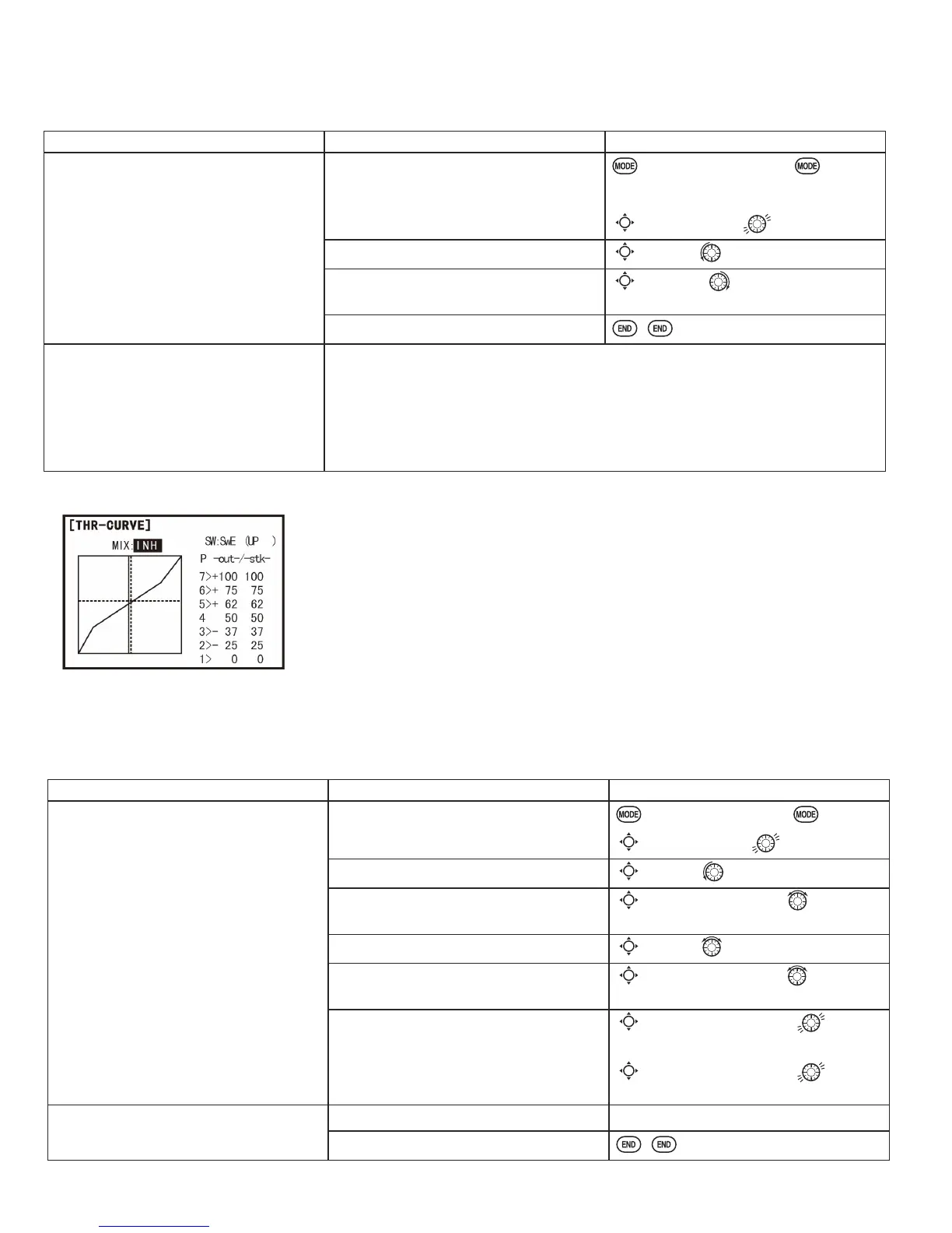
Throttle curve (
THR-CURVE
)(
ACRO
):
This function adjust the throttle operation curve for optimum the engine speed
to throttle stick movement.
NOTE: If the throttle
EXP
function is activated, you can not use
THR-CURVE
function simultaneously.
Adjustability:
• Separate curves for each switch position are available.
• Moving and deleting the curve point: The curve point (
-stk-
) can be moved to the left or right by turning the DIAL (up to
LQIURQWRIWKHDGMRLQLQJSRLQWDQGGHOHWHGUHWXUQHGE\SUHVVLQJWKHDIAL for one second alternately.
GOAL of EXAMPLE: STEPS: INPUTS:
Base point: Adjust base point of throttle
curve until engine idles reliably.
-out-
: output, servo position.
-stk-
: curve point, stick position.
Open the
THR-CURVE
function.
for 1 second.
(If
BASIC
, again.)
C
to
THR-CURVE
.
Activate the function.
C
to
MIX
. to
ON
.
$GMXVWWKH¿UVWSRLQW
C
to point 1 (
-out-
). to desired
throttle servo position.
Optional: Assign the switch.
C
to
SW
. to desired switch.
Optional: Move the curve point.
(Ex: point 3)
C
to point 3 (
-stk-
). to desired
curve point to move to left or right.
Optional: Delete the curve point.
And return the curve point.
(Ex: point 3)
C
to point 3 (
-stk-
). for one
second to delete the curve point.
C
to point 3 (
-stk-
). for one
second to return.
Next point: Adjust the next point. Repeat as needed.
Close.