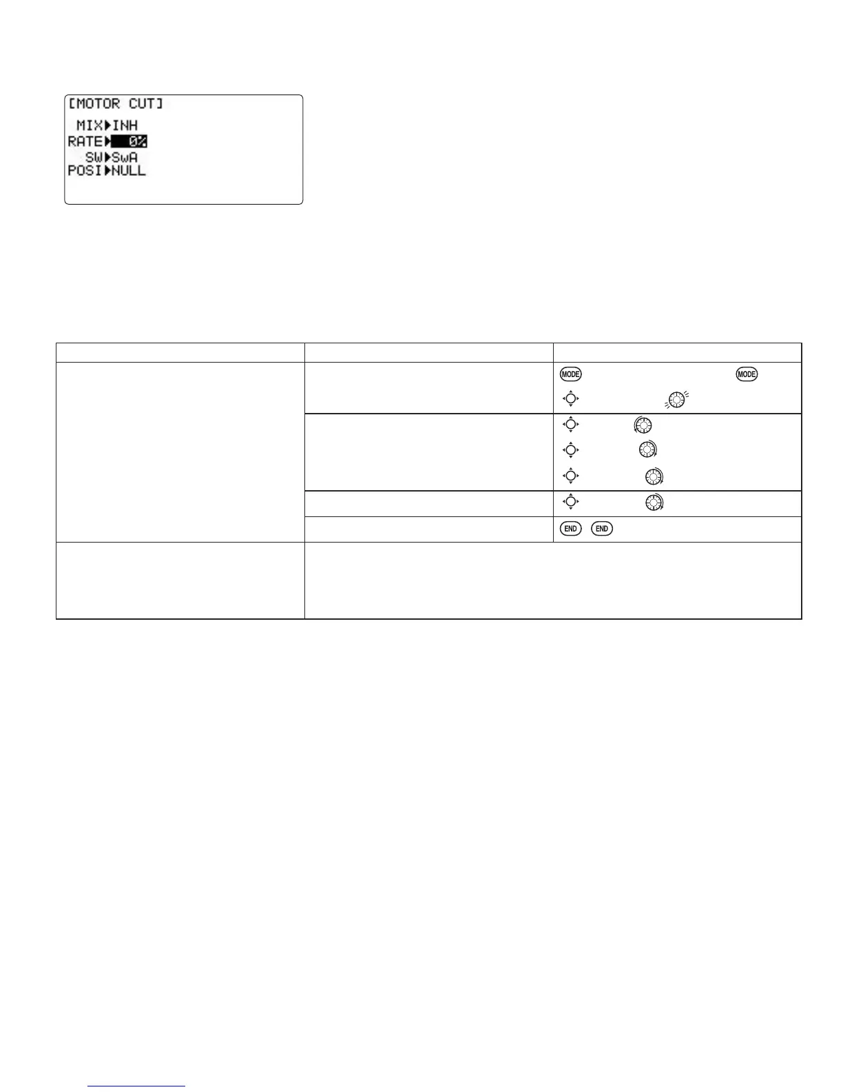
Motor cut function (
MOTOR CUT
) (
GLID
SURYLGHVDQ HDV\ ZD\WRVWRSWKH PRWRU E\ÀLSSLQJD VZLWFK UHJDUGOHVVRIWKH
AIRBRAKE STICK position. The servo movement is largest at -30%.
The switch's location and direction must be chosen. It defaults to
NULL
to avoid
accidentally assigning it to a switch, which might result in an unintentional dead
VWLFNLQÀLJKW
Adjustability:
•
RATE
range of -30 to +30. The servo movement at 0% is maximum slow position of AIRBRAKE STICK. The servo
movement is largest at -30%.
• SWITCH A-H fully assignable. Also LOGIC SW (Lsw1 to 3) may be assigned.
•
POSITION
fully assignable, including
NULL
(mix always off) and
Up&Cntr
and
Cntr&Dn
to activate the mix in 2 separate
positions of the same SWITCH.
GOAL of EXAMPLE: STEPS: INPUTS:
Decrease the rate to stop the motor
ZLWKWKHÀLSRIDVZLWFK1RWHWKDW\RX
MUST assign a switch. The default is
NULL
.)
Open
BASIC
menu, then open
THR-CUT
function.
for 1 second.
(If
ADVANCE
, again.)
C
to
THR-CUT
.
Activate the function. Choose desired
switch, and the position which activates
the function.
C
to
MIX
. to
OFF
or
ON
.
C
to
SW
. to desired switch.
C
to
POSI
. to desired position.
C
to
RATE
. until turns off.
Close.
Where next? 6HWXSGXDOWULSOHUDWHVDQGH[SRQHQWLDO
D/R
,
EXP
): see p. 30.
Set up
TRAINER
functions: see p. 34.
*Also LOGIC SW(Lsw1 to 3) may be assigned. Set up
LOGIC SW
: See p. 26.
GLIDER ADVANCE MENU
Varied wing types and tail types (twin aileron servos, twin elevator servos, elevon, v-tail, etc).
•
FLAPERON
(
GLID 1A+1F
RQO\DLOHURQVHUYRVRSHUDWHLQRSSRVLWHGLUHFWLRQVDVDLOHURQVDQGVDPHGLUHFWLRQDVÀDSV
•
CAMBER FLAP
SURYLGHVFDPEHUPRYHPHQWRUWULPPLQJRIÀDSV
• For sailplanes, this function is also used as wing camber. The amount depends on the model, but usually a small
amount (less than 10%) is preferred, since too much camber produces excess drag. Don’t use more than about
´ WUDYHO XS RU GRZQ IRU JOLGHU FDPEHU 6RPH DLUIRLOV VXFK DV WKH 5* VKRXOG EH ÀRZQ ZLWK 12 UHÀH[
camber. Be sure to consult your model’s manual for guidelines.
• Note that even though you may make
CAMBER FLAP
active while using
AILE-DIFF
, it will not have any effect. The
21/<IXQFWLRQWKDWDOORZVFRQWURORIWKHDLOHURQVDVÀDSVLQWKH
AILE-DIFF
FRQ¿JXUDWLRQLVDLUEUDNHEXWWHUÀ\
• Aileron Differential (
AILE-DIFF
): allows twin aileron servos to provide differential down travel from up travel.
• Using a 5-channel receiver with
FLAPERON
and
AILE-DIFF
.
•
ELEVON
IRUÀ\LQJZLQJV
•
V-TAIL
: for models with 2 servos operating together to create roll and pitch control.
•
AILEVATOR
: not available in
GLID
model types.
 Loading...