36
HELI
models only:
OFFSET
is available in the idle ups. If
OFFSET
is inhibited, adjustment of the TRIM LEVERS will adjust
WKHWULPVIRUDOOÀLJKWFRQGLWLRQV,I
OFFSET
is active, then moving the trims within any one condition will effect only that
condition. See
OFFSET
, p. 81.
Trim reset (
RESET
): electronically centers the trims to their default values. Note that the
SUB-TRIM
settings and the trim
STEP
rate are not reset by this command.
GOAL of EXAMPLE: STEPS: INPUTS:
Reset trims to neutral after having
adjusted all linkages.
NOTE: This is one of several
functions for which the radio requires
FRQ¿UPDWLRQWRPDNHDFKDQJH
Open
BASIC
menu, then open
TRIM
submenu.
for 1 second.
(If
ADVANCE
, again.)
C
to
TRIM
.
Request DQGFRQ¿UPWKHUHVHW.
for 1 second.
Beep sounds.
Close.
Where next? Adjust
SUB-TRIMs
: see p. 36.
Adjust trim rate (
STEP
): see below.
Adjust
END POINTs
: see p. 27.
6HWXSGXDOWULSOHUDWHVDQGH[SRQHQWLDO
D/R
,
EXP
): see p. 30.
Trim step (
STEP
): changes the rate at which the trim moves when the TRIM LEVER is activated. It may be set from 1 to
40 units, depending on the characteristics of the aircraft. Most ordinary aircraft do well at about 2 to 10 units. Generally
ODUJHUWULPVWHSVDUHIRUPRGHOVZLWKODUJHFRQWUROWKURZVRUIRU¿UVWÀLJKWVWRHQVXUHVXI¿FLHQWWULPWRSURSHUO\FRUUHFWWKH
PRGHO6PDOOHUWULPVWHSVDUHODWHUXVHGWRDOORZYHU\¿QHDGMXVWPHQWVLQÀLJKW
GOAL of EXAMPLE: STEPS: INPUTS:
Double the sensitivity (larger step) ofthe
AILERON TRIM LEVERS for a first
flight of an aerobatic model to ensure
sufficient range to trim the model for
OHYHOÀLJKW
Open
TRIM
submenu and choose the
STEP
you wish to change. (Ex: aileron)
for 1 second.
(If
ADVANCE
, again.)
C
to
TRIM
.
Adjust the size of the step.
(Ex: incr. to
8
)
C
to
AILE
. to
8
.
Repeat as desired for other channels.
C
to
ELEV
. to new setting.
Repeat as needed.
Close.
Where next? Adjust sub trims: see p. 36.
Adjust
END POINTs
: see p. 27.
6HWXSGXDOWULSOHUDWHVDQGH[SRQHQWLDO
D/R
,
EXP
): see p. 30.
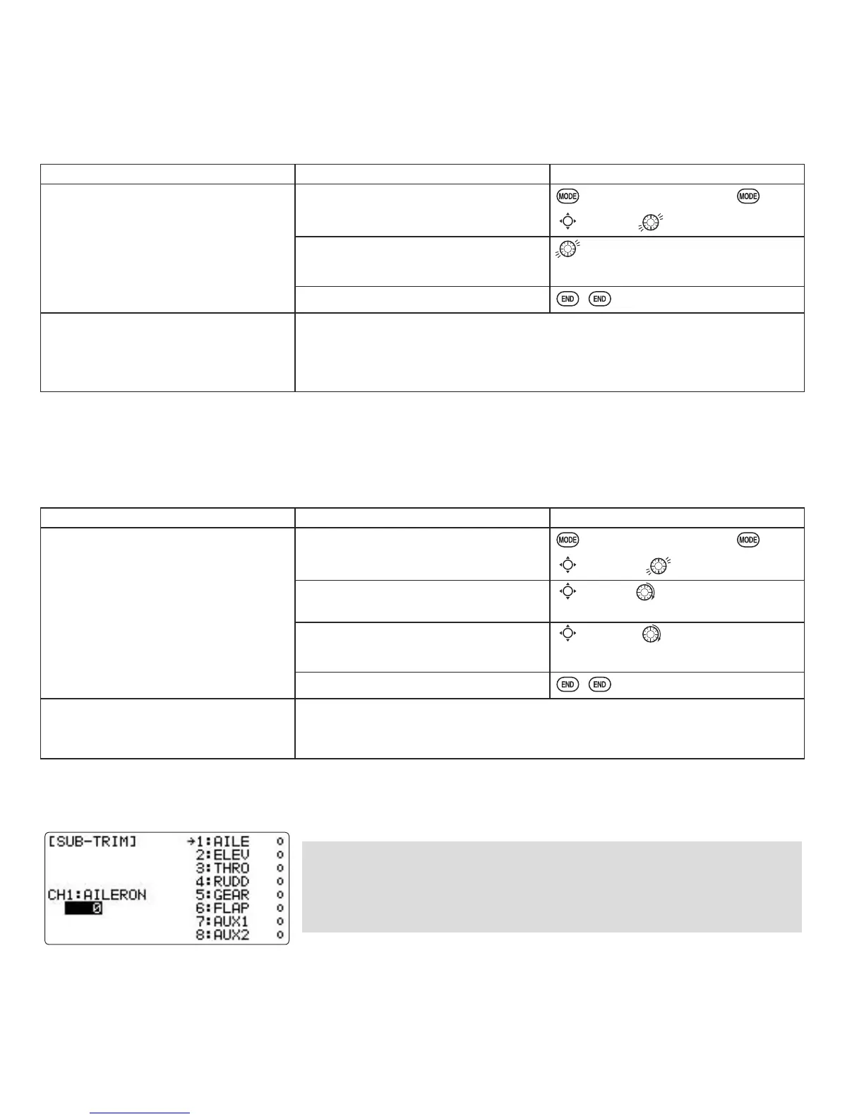
SUB-TRIM
: makes small changes or corrections to the neutral position of each servo. Range is -120 to +120, with 0 setting,
the default, being no
SUB-TRIM
.
We recommend that you center the digital trims before making
SUB-TRIM
changes, and that you try to keep all of the
SUB-TRIM
values as small as
possible. Otherwise, when the
SUB-TRIMs
are large values, the servo's range
of travel is restricted on one side.
The recommended procedure is as follows:
• measure and record the desired surface position;
• zero out both the trims (
TRIM RESET
menu) and the
SUB-TRIMs
(this menu);
• mount servo arms and linkages so that the control surface’s neutral is as correct as possible; and
• use a small amount of
SUB-TRIM
WRPDNH¿QHFRUUHFWLRQV
 Loading...