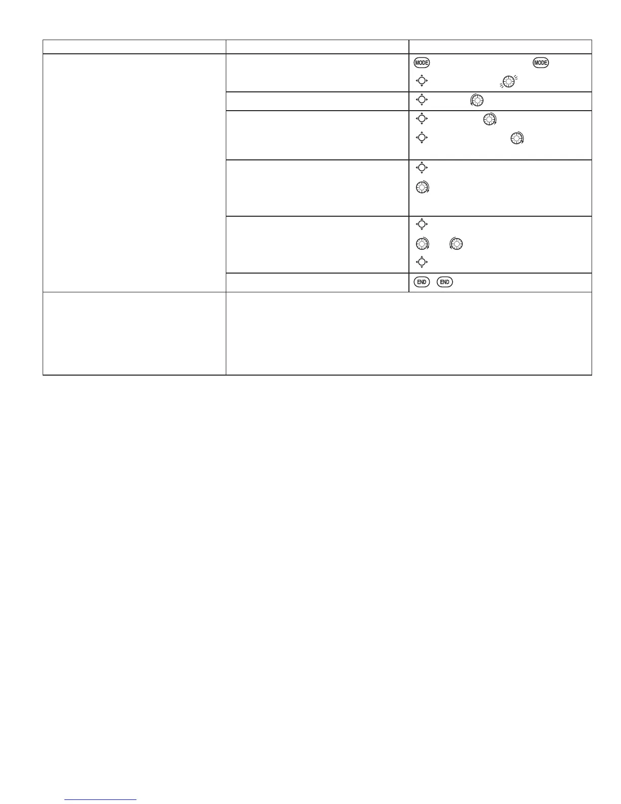
GOAL of EXAMPLE: STEPS: INPUTS:
Set up a governor to use
both channels into the receiver
and switch between the governor
settings automatically when changing
conditions. Consider setting the battery
Fail Safe settings and other helpful
functions on the GV-1 itself.
Open and activate the
GOVERNOR
function.
for 1 second.
(If
BASIC
, again.)
C
to
GOVERNOR
.
Activate the function.
C
to
MIX
. to
ACT
.
Optional: change cut-off channel
to channel 8 and assign switch and
direction for on/off (channel 8).
C
to cut-
CH
to
+CH8
.
C
to cut-
SW
. to desired
SWITCH.
Optional: change switch assignment to
select governor settings.
Ex: select switch that selects the
conditions.
C
to
SW
.
to
Cond
.
Adjust governor speed settings per
switch position or condition as needed.
(Ex: defaults are fine.) Allows head
speed adjustment from transmitter.
C
to each
Cond
position.
or as needed.
C
to next
Cond
position. Repeat.
Close the function.
Where next?
GYRO
: see p. 85.
Adjust FailSafe (
F/S
) settings (p. 37).
$GMXVWLGOHXSFROOHFWLYHSLWFKFXUYHIRUVDPHUDWHVRIFOLPEXSULJKWLQYHUWHG
See p. 80.
$GMXVWHOHYDWRUDLOHURQ UHVSRQVH WRILW \RXU IO\LQJVW\OH VHH
D/R
,
EXP
and
END
POINT
SWASH AFR
: p. 30, 27, 75.
functions on the Governor itself.

 Loading...