www.raisecom.com User Manual
16
When channel number of a sub-card is configurable, RC3000 will distribute channels for each slot
as:
8-line mode 10-line mode
SLOT1: 1-8 channels SLOT1: 1-10 channels
SLOT2: 9-16 channels SLOT1: 11-20 channels
SLOT3: 17-24 channels SLOT1: 21-30 channels
Note: The last slot allocates the number of: timeslots according to the first mode of E1; when
PCM30, occupy 17-30 channels; when PCM31, occupy 17-31 channels. The principle of allocating a
specific time slot, refer to Function Description behind.
All sub-board support hot-swap and this operation will not affect device work status.
4.3.2 Up-link interface
There is one line-board slot for each RC3000 and the device cannot work without line-board. You
must confirm the type of line-board when ordering because it is fixed and not hot-swap:
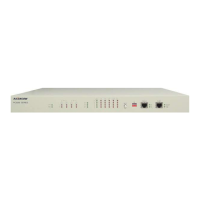
1. Optical line-board + 100M Ethernet interface: RC3000-OPT-FE
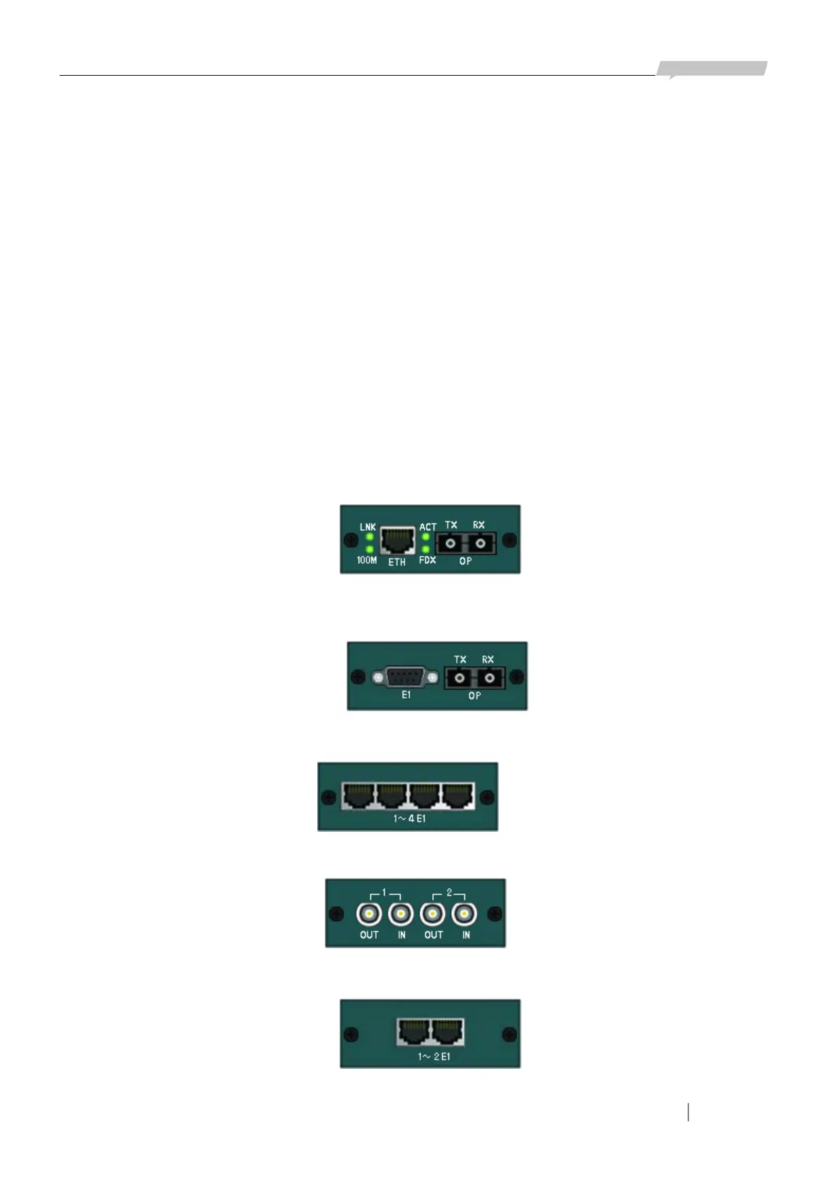
2. Optical line-board + 2E1 interface: RC3000-OPT-2E1 (special DB9 connector of E1 interface to
transfer 2E1 lines)
3. Line-board with 4 E1 interfaces: RC3000-4E1
4. Line-board with unbalanced 2E1 interfaces: RC3000-2E1
5. Line-board with balanced 2 E1 interfaces: RC3000-2E1-BL
Figure 4-4
Figure 4-5
Figure 4-6
Figure 4-7
Figure 4-8