www.raisecom.com User Manual
38
5.17.1 Timeslot setting rules
RC3000-SUB-DV24 is a sub-card with fixed timeslot bandwidth, it is fixed to take up 8 timeslots,
every path can set relevant channels according to bandwidth. Corresponding relationship as below
table shows:
Path 1 2 3 4
Bandwidth 64k (occupy channel) 1 3 5 7
Bandwidth 128k (occupy channel) 1, 2 3, 4 5, 6 7, 8
5.18 Function of RC3000-SUB-DC64K
RC3000-SUB-DC64K is 4 line 64K date card, the interface symbol rate is 265KBps .each card has 4
channels, and occupies 4 line 64K channels (each channel occupies 1 line 64K channel), and the
number of channels occupied is determined by hardware without change. Interface is made up of 2
RJ45; each RJ45 provides 2 user interfaces.
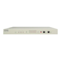
5.18.1 Panel diagram
Figure 40
5.18.2 Indicator description
LOS: ON: signal loss alarm; OFF: no warning; When the channel use the internal error tester to test,
the indicator will express LOS alarm in tested lines, ON: alarm; OFF: no warning.
AIS: ON: the signal is the whole "1" warning, OFF: no warning. When the channel use the internal
error tester to test, the indicator will indicator that the test results, ON: error, OFF: no error.
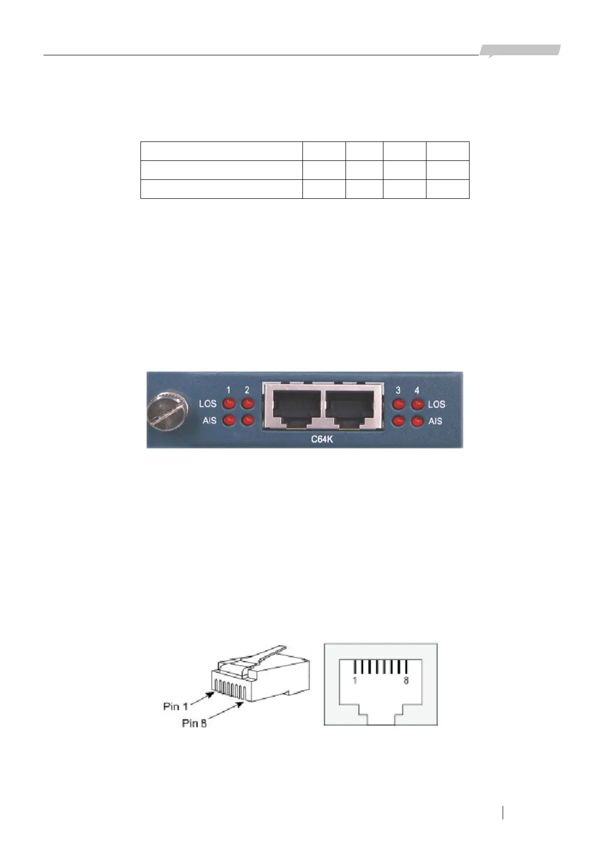
5.18.3 Interface diagram
RJ45 connector RJ45 socket
Figure 41