www.raisecom.com User Manual
29
you list the cross connect table first to avoid mistakes.
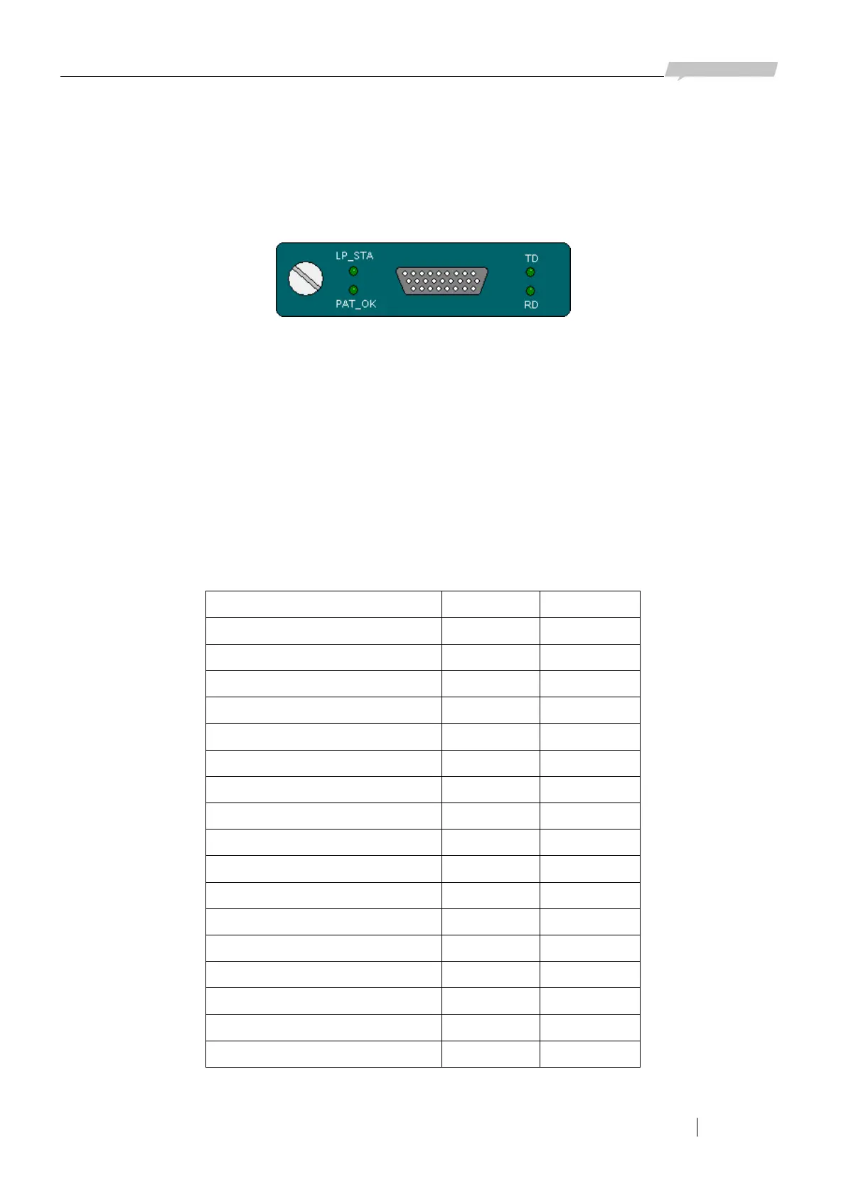
5.7.2 Definition of V35 interface
V35 interface uses V35/HDB26 female connector and can be connected to standard DTE cable as in
following figure:
Figure 5-13
Indicator lights are all green:
TD: V35 data Tx indicator
RD: V35 data Rx indicator
LP_STA: loop indicator. ON: local internal loop
PAT_OK: In normal work status is OFF.
ON: RCR check normally
OFF: abnormal
Interface definition:
Name Input/output Pin number
Chassis Ground — CGND - 1
Signal Ground — GND - 7
Receive Data (A) — RD(A) O 3
Receive Data (B) — RD(B) O 21
Receive Timing (A) — RCK(A) O 17
Receive Timing (B) — RCK(B) O 25
Send Data (A) — TD(A) I 2
Send Data (B) — TD(B) I 11
Send Timing (A) — TCK(A) O 15
Send Timing (B) — TCK(B) O 23
Terminal Timing (A) — SCTE(A) I 24
Terminal Timing (B) — SCTE(B) I 16
Request to Send — RTS I 4
Clear to Send — CTS O 5
Data Set Ready — DSR O 6
Data Carrier Detect — DCD O 8
Data Terminal Ready — DTR I 20
Note: I—input; O—output