www.raisecom.com User Manual
23
Signaling and Pin definition of LINK DOWN interface:
Pin number Signal Explanation
3 TXD Rx of RC3000
7 RXD Tx of RC3000
4,8 GND Ground of RC3000
d. Definition of balanced RC3000-4E1 E1 interface:
Balanced E1 interface is RJ45 interface, and the Signaling and Pin definition are:
Pin number Signal Explanation
1 OUT+ Positive Tx of balanced E1 interface
2 OUT- Negative Tx of balanced E1 interface
4 IN+ Positive Rx of balanced E1 interface
5 IN- Negative Rx of balanced E1 interface
5.2 Function of RC3000-SUB-DS
FXS is a user audio card with feed and feed ring and can be connected to exterior line interface of
FBX. There are 8 channels of a FXS and the channel number is decided by hardware, unchangeable.
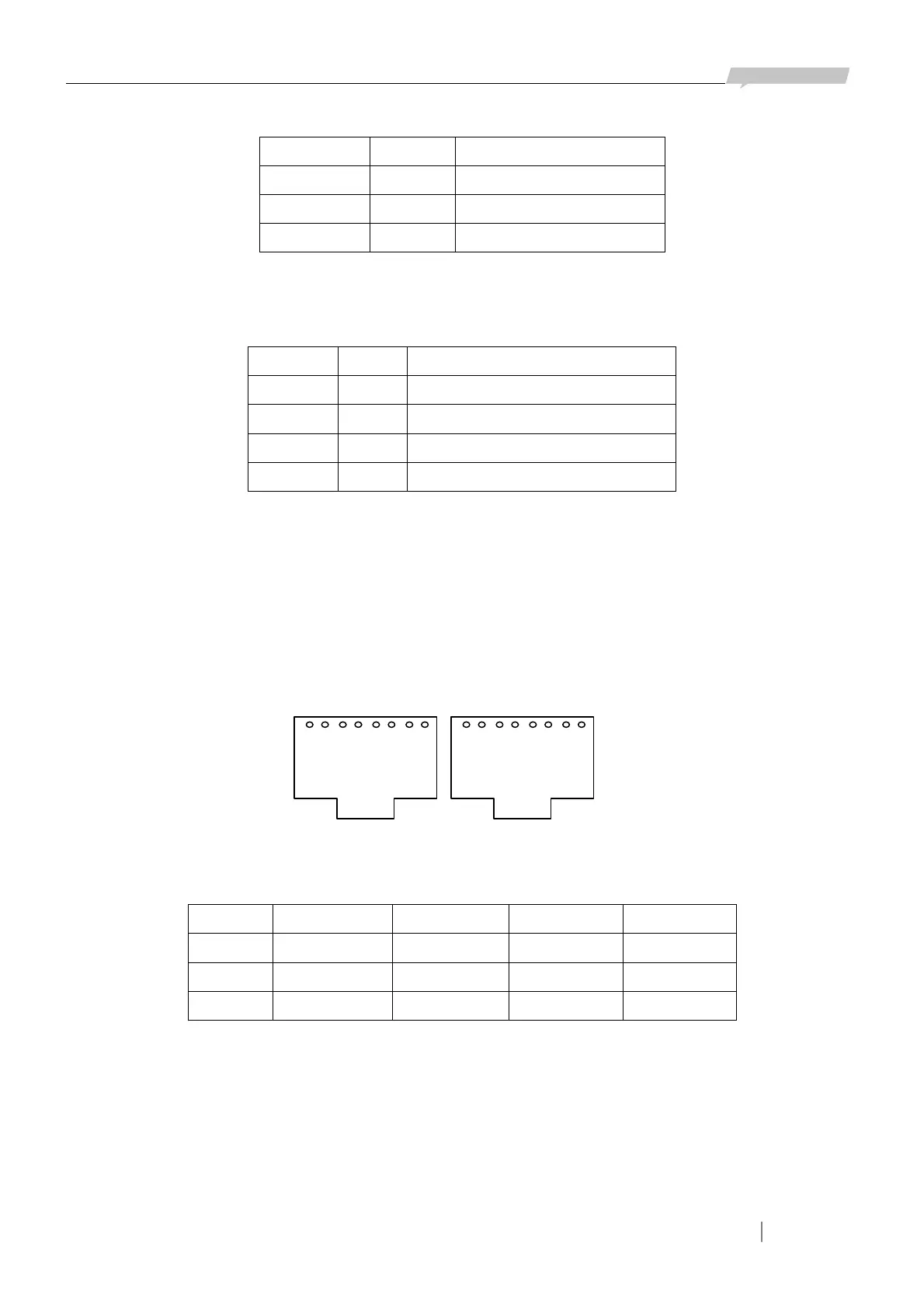
Two RJ45 interfaces make up of the 8 channels (each RJ45 interface has four channels). Definition
of RJ45 interface is as follows:
Channel 1 2 3 4
Pin No. RJ45-1, 1T,2R RJ45-1, 3T,4R RJ45-1, 5T,6R RJ45-1, 7T,8R
Channel 5 6 7 8
Pin No. RJ45-2, 1T,2R RJ45-2, 3T,4R RJ45-2, 5T,6R RJ45-2, 7T,8R
1 2 3 4 5 6 7 8
1 2 3 4 5 6 7 8
Figure 5-4
RJ45-1 RJ45-2