Preparing for Use
R&S
®
NRPxxS(N)
15User Manual 1177.5079.02 ─ 10
a) Connect the R&S NRP‑ZKU cable to the power sensor.
b) Connect the R&S NRP‑ZKU cable to the computer.
c) Connect the power sensor to the signal source.
2. On the computer, start a software application to view the measurement results.
See Chapter 5, "Operating Concepts", on page 27.
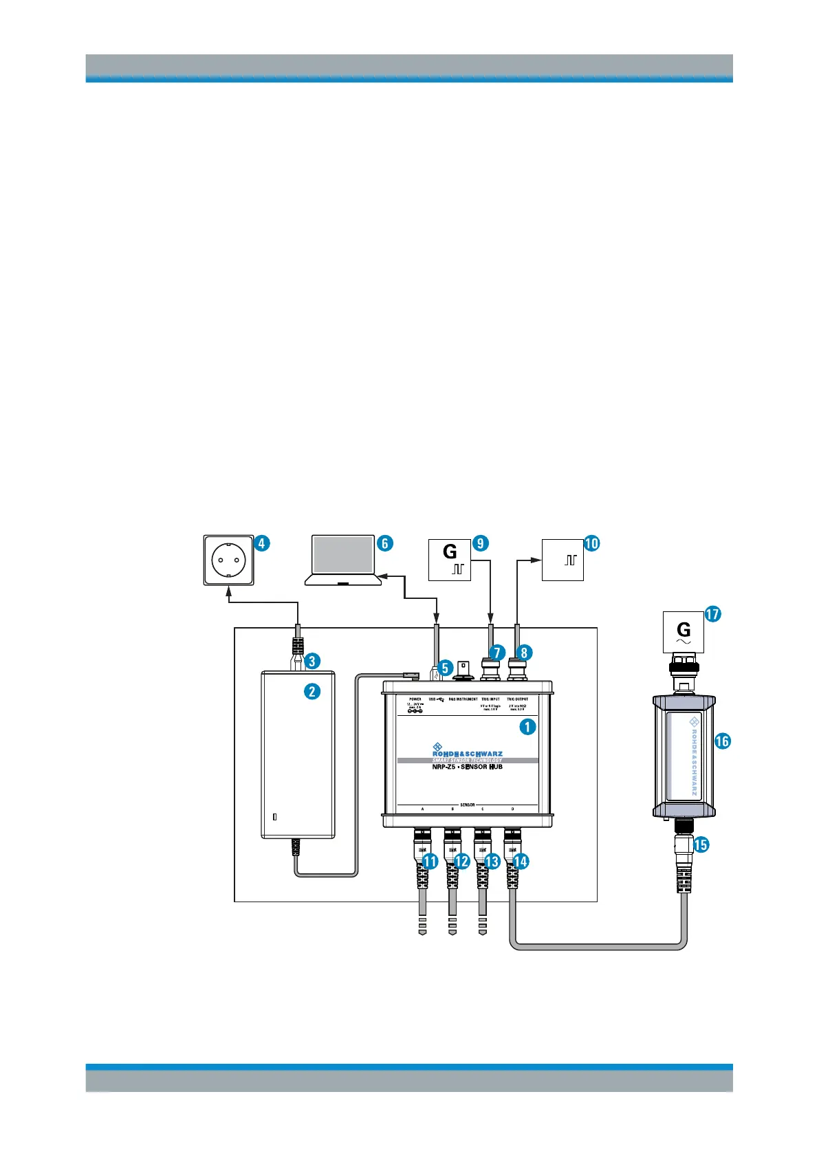
3.5.1.2 R&S NRP‑Z5 Sensor Hub Setup
The R&S NRP‑Z5 sensor hub (high-speed USB 2.0) can host up to four R&S
NRPxxS(N) power sensors and provides simultaneous external triggering to all con-
nected sensors.
Required equipment
●
1 to 4 R&S NRPxxS(N) power sensors
●
1 R&S NRP‑ZK6 cable per sensor
●
R&S NRP‑Z5 sensor hub with external power supply unit and USB cable
●
BNC cables to connect the trigger input and trigger output signals (optional)
Setup
TTL /CMOS
TTL /CMOS
NRP
3-Path Diode Power Sensor
MHz to GHz, 100 pW to 200 mW (−70 dBm to +23 dBm)
SMART SENSOR TECHNOLOGY
Figure 3-2: Setup with an R&S NRP-Z5 sensor hub
Connecting to a Computer
 Loading...


