CHAPTER 1
10 AccuFlow™ Vortex and AccuFlow™ HP+ Installation and Operation Manual
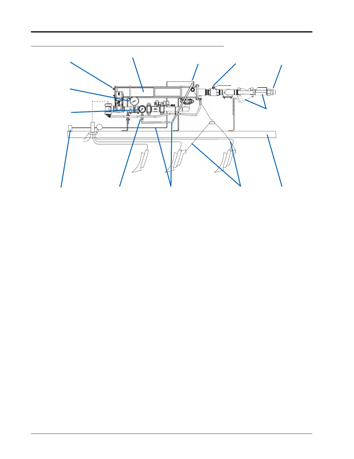
FIGURE 2. Example Discharge and Shutoff Component Locations (Side View)
NOTE: Equipment configurations may vary. Figure 2 on page 10 is an example diagram of an anhydrous
ammonia (NH
3
) system. Operators must familiarize themselves with the system, bleed valve locations,
and procedures before charging the system with NH
3
.
Primary
Bleed Valve
Secondary Bleed
Valve
Vapor Hoses Toolbar
Bleed Circuit
Pressure Hose
Connection
Pressure
Gauge
Temperature
Gauge
Vortex Cooler Bleed Circuit Vapor
Hose Connection
Emergency
Shut-Off Valve
Bleed Lines
Hose
Breakaway
System Strainer(s)
and Check Valve(s)