CHAPTER 5
54 AccuFlow™ Vortex and AccuFlow™ HP+ Installation and Operation Manual
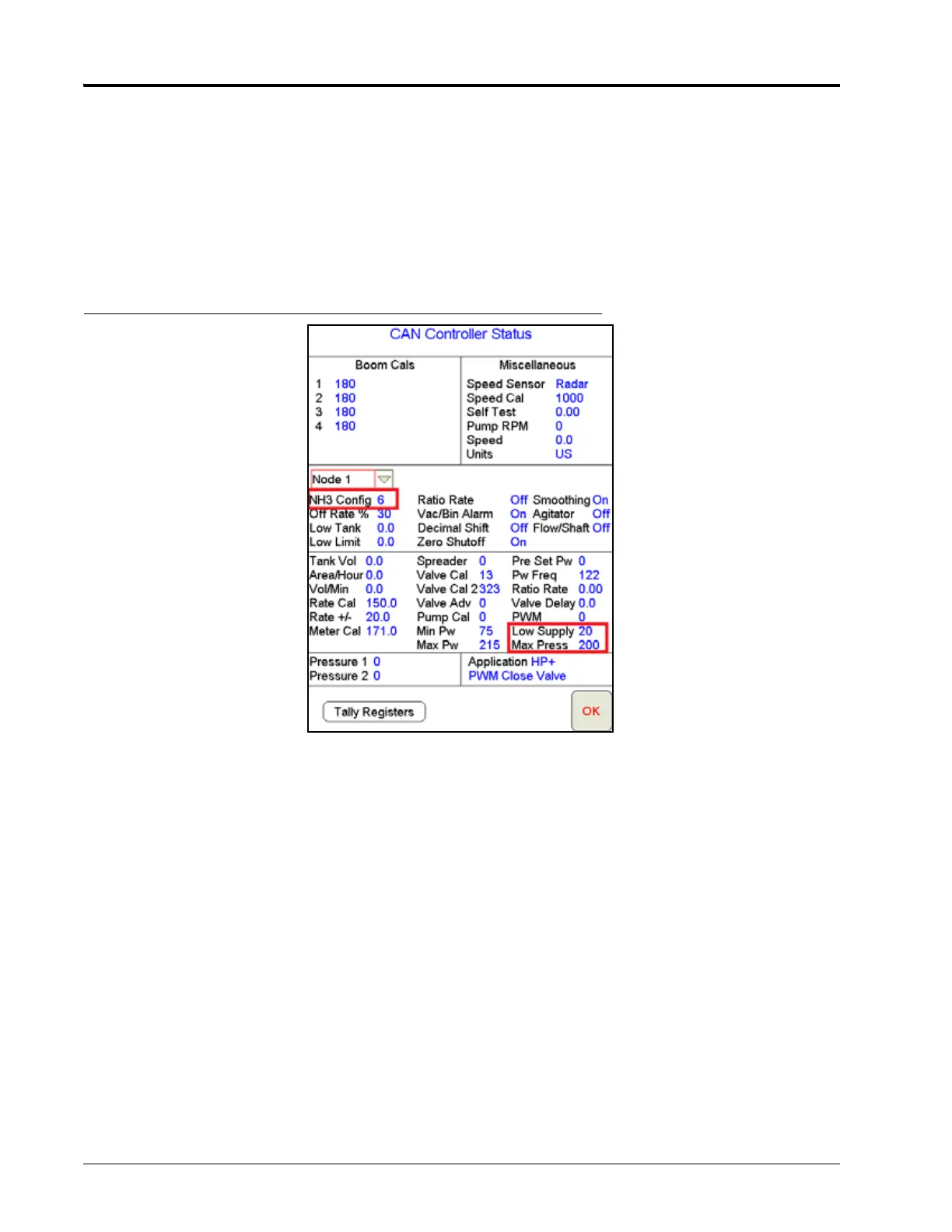
a. NH
3
Config will enable remote switch & section feedback if desired.
i. 3 - remote prox sensor enabled, section feedback disabled
ii. 4 - remote prox sensor disabled, section feedback disabled
iii. 5 - remote prox sensor enabled, section feedback enabled
iv. 6 - remote prox sensor disabled, section feedback enabled (default setting)
FIGURE 2. CAN Controller Status
b. ‘Low Supply’ will generate an error message if pump inlet pressure drops below set value (20 psi default;
adjustable from 0-50 psi from Node 1 Settings screen). A setting of zero disables the feature.
c. Max Press limits the pressure the pump can generate (200 psi default; adjustable from 0-250 psi). Once
the 'Max Press' limit is reached the control will temporarily turn the pump down. A setting of zero disables
the feature.
6. AccuFlow HP+ has two pressure transducers; P2 at the pump inlet (Vortex cooler) and P1 at the gauge tree
manifold. They are used to monitor pump status and performance.