AccuFlow™ HP+ Calibration and Operation: Programming HP+ Rate Control - Viper Pro 55
ACCUFLOW™ HP+ CALIBRATION AND OPERATION
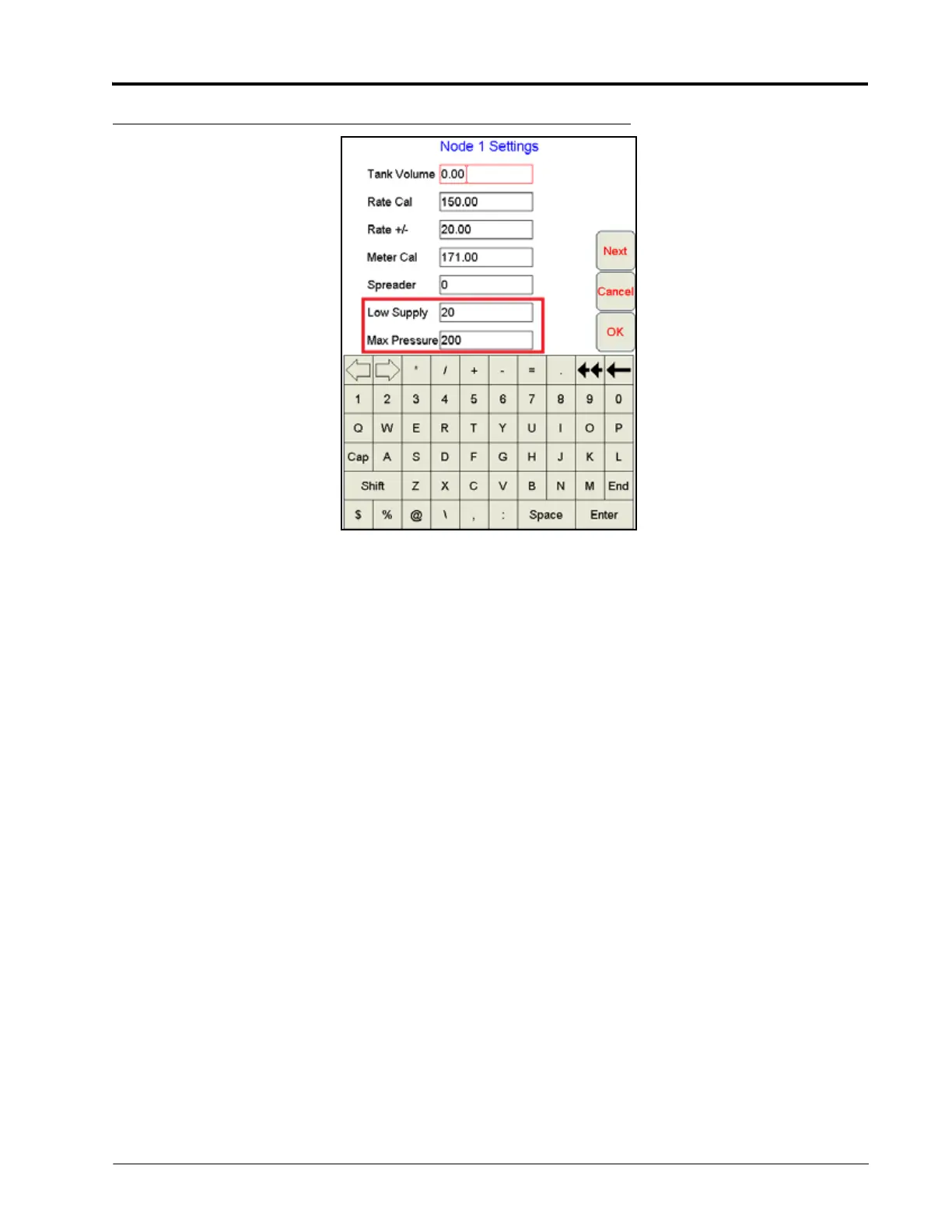
FIGURE 3. Node 1 Settings
7. Pressure Transducer Cal - Calibrate pressures making sure P1 is the transducer at the gauge tree manifold and
P2 is the transducer at the cooler. Complete transducer calibration after the AccuFlow system is fully charged
and ready for operation. Refer to Viper Pro manual for steps on pressure transducer calibration.
IMPORTANT: Pressure transducers must be accurately calibrated for Low Supply, Max Pressure and Pump Fault errors to
work properly. Cal both transducers to the same pressure value as indicated on the AccuFlow system
pressure gauge (should also be the same as tank pressure).
8. Viper Pro will now display valve drive status in addition to PWM duty cycle. A '+' symbol is displayed when the
control is sending an increase command to the valve (as shown in red box) with a '-' displayed for decrease.
This can be a useful tool for diagnostics and troubleshooting.