4.3Powerconnection
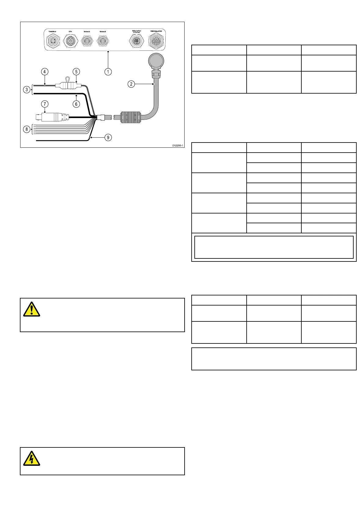
1.Multifunctiondisplayconnections.
2.Poweranddatacable.
3.Connectionto12/24Vpowersupply(e7/e7Dis12Vonly).
4.Redcable(positive).
5.Fuse.
6.Blackcable(negative).
7.Videoinputcable.
8.NMEA0183datacables.
9.Shield(drain)wire(thinblackwire;mustbeconnectedtoRF
groundpoint).
Powerdistribution
Raymarinerecommendsthatallpowerconnectionsaremadeviaa
distributionpanel.
•Allequipmentmustbepoweredfromabreakerorswitch,with
appropriatecircuitprotection.
•Allequipmentshouldbewiredtoindividualbreakersifpossible.
Warning:Productgrounding
Beforeapplyingpowertothisproduct,ensureithas
beencorrectlygrounded,inaccordancewiththe
instructionsinthisguide.
Grounding—Dedicateddrainwire
Thepowercablesuppliedwiththisproductincludesadedicated
shield(drain)wireforconnectiontoavessel’sRFgroundpoint.
ItisimportantthataneffectiveRFgroundisconnectedtothe
system.Asinglegroundpointshouldbeusedforallequipment.
Theunitcanbegroundedbyconnectingtheshield(drain)wireof
thepowercabletothevessel’sRFgroundpoint.Onvesselswithout
anRFgroundsystemtheshield(drain)wireshouldbeconnected
directlytothenegativebatteryterminal.
Thedcpowersystemshouldbeeither:
•Negativegrounded,withthenegativebatteryterminalconnected
tothevessel’sground.
•Floating,withneitherbatteryterminalconnectedtothevessel’s
ground
Warning:Positivegroundsystems
Donotconnectthisunittoasystemwhichhaspositive
grounding.
Powercable
Thedisplayissuppliedwithacombinedpoweranddatamulticable,
thiscanbeextendedifrequired.
Powercablesavailable
CablePartnumberNotes
1.0m(3.3ft)Powerand
datacable
R62379
1.0m(3.3ft)Right
angledpoweranddata
cable
R70029
Cableextension
Thefollowingrestrictionsapplytoanyextensiontothepowercable:
•Cablemustbeofasuitablegaugeforthecircuitload.
•Eachunitshouldhaveitsowndedicatedpowercablewiredback
tothedistributionpanel.
Totallength(max)SupplyvoltageCablegauge(AWG)
12V18
0–5m(0–16.4ft)
24V20
12V14
5–10m(16.4–32.8ft)
24V18
12V12
10–15m(32.8–49.2ft)
24V16
12V12
15–20m(49.2–65.5ft)
24V14
Note:Thesedistancesarefora2wirepowercablerunfromthebatteryto
thedisplay(approximatelythedistancefromthebatterytothedisplay).To
calculatetheroundtriplength,doublethegurestatedhere.
Breakers,fusesandcircuitprotection
Thepowercableincludesanin-linefuse.Itisrecommendedthat
youtanadditionalthermalbreakerorfuseatthedistributionpanel.
DisplayFuseratingThermalbreakerrating
•e7/e7D7Ain-linefusetted
withinpowercable.
5A(ifonlyconnecting
onedevice)
•c95/c97/c125/
c127/e95/e97/
e125/e127
10Ain-linefusetted
withinpowercable.
7A(ifonlyconnecting
onedevice)
Note:Thesuitablefuseratingforthethermalbreakeris
dependentonthenumberofdevicesyouareconnecting.Ifin
doubtconsultanauthorisedRaymarinedealer.
Cablesandconnections33
 Loading...