2-16
hsb
2
Plus Series Fishfinders
Display Unit
Connection
• Combined depth/speed/temp transducers have a 7 pin female connector.
Attach the transducer cable connector directly to the display unit.
• Combined speed/temperature transducers have a 3 pin female connector
that requires the use of an additional Y-shaped cable (Raymarine part num-
ber E66022) to attach to the 7 pin connector on the display. This Y-cable is
included with your speed/temperature transducer.
Attach the 7 pin female connector on the Y-cable to the display unit then
attach the transducer cable to the 3 pin male connector on the Y-cable.
• Depth-only transducers have a 7 pin female connector.
Attach the transducer cable connector directly to the display unit.
or
If being installed in conjunction with a speed/temperature transducer,
attach the 7 pin female connector on theY-cable to the display then attach
the transducer cable to the 7 pin male connector on the Y-cable.
Note: If your system requires both a Y-cable and a transducer extension ca-
ble, ensure that you connect the Y-cable to the display unit and the extension
cable to the transducer.
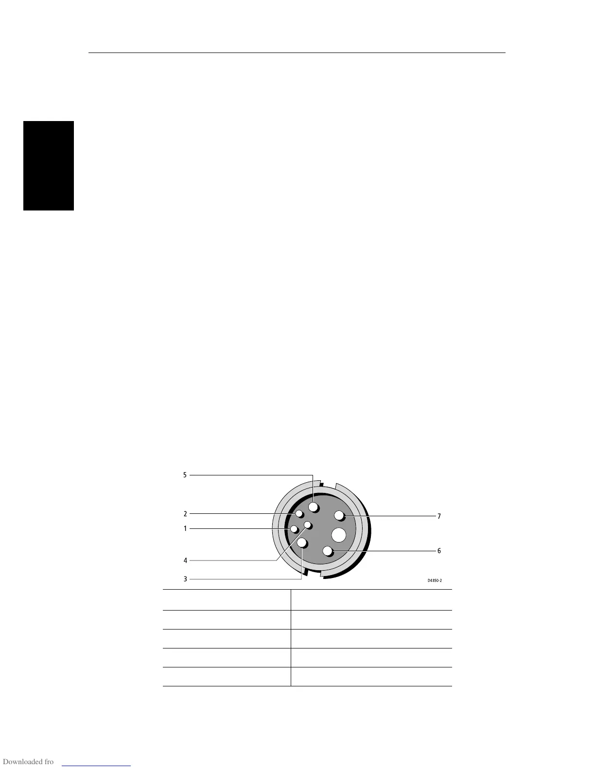
The connector pins are shown in the following diagram, together with the
connections and wire colors; this is information is provided as an aid to fault
diagnosis.
CAUTION:
Do not cut the transducer cable or remove the connector. Do not try to
shorten or splice the cable. If the cable is cut, it cannot be repaired.
Cutting the cable will also void the warranty.
Figure 2-9: Fishfinder Transducer Connector
Pin No. Function Color Pin No. Function Color
1 Speed Red 5 Speed/Temp Ground Brown
2TempWhite6+ Depth Blue
3 Shield Drain 7 - Depth Black
4SenseGreen
5
1
2
3
4
7
6
D4850-2