Chapter 2: Installation 17
If the power cable must be extended, estimate the length of cable between
the vessel’s main power source and the connector block, then select the
correct wire size determined by the distance as indicated below.
The DC power input should be connected to the POWER cable at the
bottom of the chartplotter. The cable colors are detailed below.
➤ Connect to the power supply using the power cable supplied:
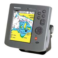
1. Connect the molded connector (with the arrow facing you) to the con-
nector on the bottom of the chartplotter. Run the free end back to the
vessel’s distribution panel or to a junction box.
Note: The molded power connector is spring-loaded to ensure a positive
lock. When removing, press down on the outer ring as you pull the con-
nector away from the RC400. This will prevent damage to the connector.
2. Cut the cable to length and connect the red wire (via a 1A quick blow
fuse) to the + battery terminal and the black wire to the – terminal.
3. Use a suitable junction box to connect to any NMEA equipment.
4. Cut any unused wires short or insulate and tape back.
CAUTION: If the power connections are accidentally reversed, the
system will not function. Use a voltmeter to check that the input
power leads are connected with the correct polarity.
Wire size AWG: 16 15 14 12 10 8
Wire size in mm
2
:
1.5 2.0 2.5 4.0 6.0 10.0
Maximum Extension (feet): 36 49 65 98 147 230
Maximum Extension (meters): 11.0 15.0 20.0 30.0 45.0 70.0
Pin Function Color
1DC Power In + Red
2DC Power In – Black
3NMEA In+ Brown
4NMEA In– Yellow
5NMEA Out+ Violet
6NMEA Out– White
Shield Drain/Screen (bare wire)

 Loading...
