TempTracker mod+ Hybrid Installation and Operation Manual 11
HTC# 059105-00D
• Only use the System sensor (#012187F) provided with the unit.
• The sensor wires can be extended up to 500' using a shielded 2-conductor cable
(Belden #8760 or equivalent). Do not ground the shield at the sensor but at the
panel using one of the terminals marked with an “O”.
• Do not run sensor wires in conduit with line voltage wiring.
• Install a 3/8"ID 1/2"NPT immersion well.
• If installing the system sensor on the supply, insert the sensor in a well with heat
paste approximately 5' feet past the boiler loop outlet on the common supply
header but before any major takeoffs. The sensor must be located where it sees
the output of all the boiler stages. If a boiler is piped so that the sensor does
not see its output, the TempTracker mod+ Hybrid will not sequence the boilers
correctly.
• The sensor can also be installed on the return to the boilers after all major returns
and before any boiler. However, when setting the reset ratio and the offset, the
user must consider the temperature drop across the building loop.
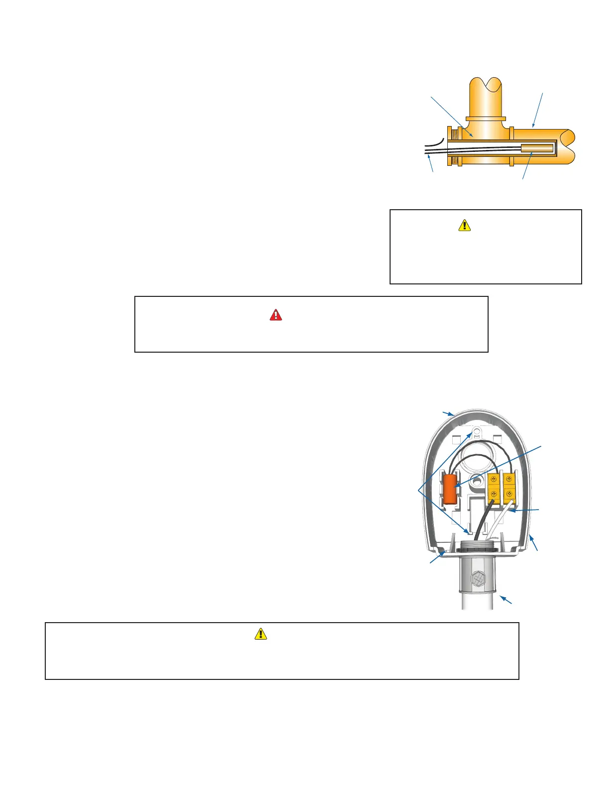
Shield
Immersion Well
3/8" ID 1/2" NPT
Immersion Heating System Sensor
Common Supply Pipe
Heating System
Sensor
Sensor Probe
Common Supply Pipe
Strap-On Heating System Sensor
Pipe Insulation
Sensor Probe
Shield
Connect
To control
If the HSS can not sense the
correct water temperature, the
TempTracker mod+ Hybrid will not
provide comfortable heat levels.
Use only the System and Outdoor Air sensors included with the control. Do
not use boiler sensors as it will cause operational problems.
• Only use the Raypak Outdoor Air Sensor group included with the unit
(#013398F).
• Locate the sensor in the shade on the north side of the building. The sensor
should never be in direct sunlight.
• Be sure the location is away from doors, windows, exhaust fans, vents, or other
possible heat sources.
• The sensor should be mounted approximately 10' feet above ground level.
• Adhere the Outdoor Label provided to the back of the sensor base.
• Use the Enclosure Base bottom knockout for the conduit. Use the locknut to hold
the conduit and enclosure base together. Screw the cover to the base.
• If screws are used to afx the enclosure to the wall, make sure to seal around the
sensor and wall except from the bottom.
• The sensor wires can be extended up to 500' using shielded 2-conductor cable
(#18/2). Do not ground the shield at the sensor but at the control using the
terminal marked with an “O”.
• Do not run sensor wires in conduit with line voltage wiring.
Determining the proper location of the Outdoor Sensor is very important. The TempTracker mod+ Hybrid
will base the heat on the outdoor temperature information it receives from this location. If the sensor is in
the sun, or covered with ice, its reading will be different from the actual Outdoor temperature (OD).
System Sensor
In Well
Shield
Not connected
Well Locknut
Sensor in Well
Well
Sensor 2-Conductor
Shielded Cable
System
Strap-On
Sensor
Shield
Not connected
Plastic
Tie-Wraps
Around Pipe
Strap-On Sensor
Immersion Sensor
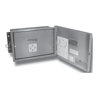
Outdoor Sensor
snap-in location
Shield
not connected
Conduit
Outdoor Label
on back of Sensor
Mounting
screws
location
Seal around
sensor and wall
Outdoor
drip-hole