TempTracker mod+ Hybrid Installation and Operation Manual 33
HTC# 059105-00D
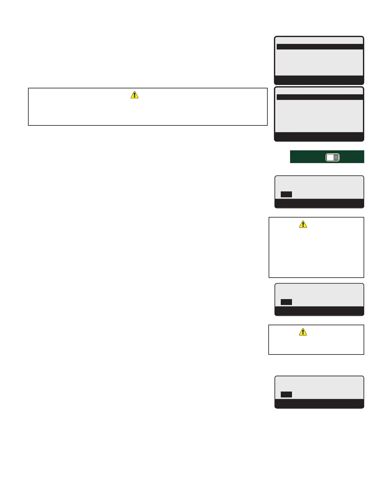
Button: MENU/<System Settings>
Settings 1 and Settings 2 menus provide access to adjusting and ne-tuning the system for
enhanced comfort and better fuel savings. The TempTracker mod+ Hybrid behaves differently
based on the selected modes. See "Startup Settings" on page 20.
-----SETTINGS1----
Setback 0
o
F
PurgeDelay 1.0min
SystemRun-On 0min
LeadRotation Time
<MoreSettings>
BACK▲▼SELECT
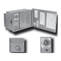
-----SETTINGS2----
StandbyTime 10min
LastStgHold 0
o
F
<LeadStages>
<StagingSettings>
<MdlatingSettings>
<Day/NightSchdule>
BACK▲▼SELECT
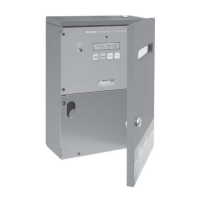
RUNPROGRAM
DO NOT APPLY ANY VOLTAGE
TO INPUT TERMINALS
3
4
5
6
7
8
9
10
11
12
13
15
14
17
16
18
20
19
21
24
23
29
25
27
26
28
32
30
31
L
N
-
+
+
T
T
O
O
RS-485
mA
GND
VLT
SYS
A
B
C
D
PWR
CUR / VLT
A
-
+
+
mA
GND
VLT
-
+
+
mA
GND
VLT
+
+
mA
22
-
GND
VLT
+
mA
TEMP
OUTDOOR
O
O
TEMP
SYSTEM
EXTENSION
MODULE
CUR / VLT
B
CUR / VLT
C
CUR / VLT
D
PROVE
/DHW
SHUTDOWN
/SETBACK
FOR ALL CIRCUITS
120VAC, 6A RESISTIVE
OUTPUT RATINGS:
1A PILOT DUTY, 15A TOTAL
115VAC 60Hz , 30VA MAX
INPUT RATINGS:
USE COPPER WIRE,
CLASS 1 WIRE ONLY.
CAUTION: RISK OF ELECTRIC SHOCK
More than one disconnect switch may be required
to de-energize the equipment before servicing.
ENCLOSED
ENERGY
MANAGEMENT
EQUIPMENT
99RA
/TSTAT
HYBRID
To be able to change the TempTracker mod+ Hybrid settings the Program/Run
Switch must be set to Program. The switch is located under the Enclosure Wiring
Cover for security. The Enclosure Wiring Cover can be secured using a lock.
Adjustablefrom0F°/0C°to75F°/42C° Default:10F°/6C°
Button: MENU/<System Settings>/Setback
• The Setback feature can be used to provide the TempTracker mod+ Hybrid with a lower
temperature Set Point when less load is required.
• The lower Set Point will appear on the main display indicating this condition.
• For example, if the calculated temperature is 180°F and the Setback is 20°F, then when in
Setback or Night Schedule, the TempTracker mod+ Hybrid will hold a Set Point of 160°F =
180°F- 20°F. See "Day/Night Schedules" on page 37.
• A typical use for the Setback is to provide less system temperature to a building during
the Night Schedule or on the weekends when people are asleep or when the building is not
occupied, but heat is still needed.
• The amount of Setback selected is subtracted from the Set Point when a Setback Input
Signal is received or the Night Time schedule setting started.
• If Setback is selected as the Shutdown/Tstat/Setback Mode (See "Shutdown/Tstat/Setback
Mode" on page 26.), the Setback will not be activated unless a Short dry-contact signal is
received on terminals (31 and 32).
• If Shutdown or Tstat is selected as the Shutdown/Tstat/Setback Mode (See "Shutdown/Tstat/
Setback Mode" on page 26.), the Setback will be activated only during the Night Schedule.
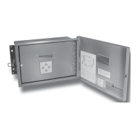
-------SETBACK-------
10
o
F
[ ]
BACK▲▼SAVE
When using Soft-Off and Last
Stage Hold, the last boiler
stage will not turn off until both
parameters have elapsed. In
this case, Soft-Off will start after
the Last Stage Hold.
Adjustablefrom0.0minto10.0min Default:1.0min
Button: MENU/<System Settings>/Purge Delay
• Many boilers go through a purge cycle before they are brought on line. When the
TempTracker mod+ Hybrid activates a boiler, it does not start to calculate its output until
the Purge Delay is over. This allows the boiler to fully come online and begin producing.
• The Purge Delay helps prevent short cycling of any newly activated burner. Once the
burner is activated, it MUST run through the entire Purge Delay period.
• The minimum Purge Delay setting MUST be set to the time required by the boiler
manufacturer. Time entry is in 0.1 of a minute (i.e. 1.5 minute will equal 90 seconds.)
• The Message Display Line will display PurgeDelay and the remaining time.
---PURGEDELAY---
1.0min
[ ]
BACK▲▼SAVE
Set Purge Delay as per boiler
manufacturer recommendation.
Adjustablefrom0minto360min Default:10min
Button: MENU/<System Settings>/System run-On
• A common use for the System Run-On is to control a system pump in a heating system.
The extra time helps transfer the boiler residual heat to the heating system.
• The System relay will energize whenever the outdoor temperature is below the Outdoor
Cutoff and the Shutdown is Open or the Tstat is closed. When the Outdoor temperature
rises 2°F above the Outdoor Cutoff or the control is switched to Summer and after the last
burner relay has de-energized, the System relay will remain energized for the System Run-
On period.
--SYSTEMRUN-ON--
10min
[ ]
BACK▲▼SAVE