TempTracker mod+ Hybrid Installation and Operation Manual 7
HTC# 059105-00D
F
H
J
Power
CAUTION:
Risk of Electric Shock.
More than one disconnect switch may be required
to de-energize the equipment before servicing.
PWR
L N
1 2
E
3 4
F
5 6
G
7 8
H
9 10
I
11 12
EXTENSION
MODULE
RS-485
Ext A
INPUT RATINGS:
115VAC 60Hz, 12VA MAX
Use Copper Conductors Only.
OUTPUT RATINGS:
120VAC, 6A RESISTIVE
1A PILOT DUTY, 15A TOTAL
FOR ALL CIRCUITS
E
G
I
Comm
Ext B
K
M
O
L
N
P
1514
VLTmA
CUR / VLT
181716
VLTmAGND
CUR / VLT
212019
VLTmAGND
CUR / VLT
242322
VLTmAGND
CUR / VLT
J
11 12
K M OL N P
E F G H
K ML N
13
GND
16
GND
19
GND
22
GND
2726
VLTmA
CUR / VLT
302916
VLTmAGND
CUR / VLT
25
GND
28
GND
I J
O P
ENCLOSED
ENERGY
MANAGEMENT
EQUIPMENT
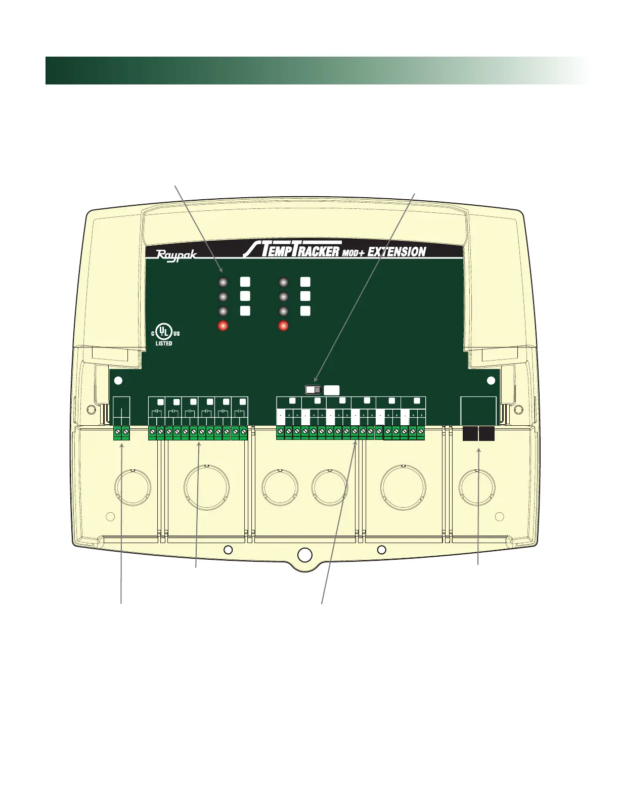
99RA
120VAC Power
Six N.O. Boiler startup relay
outputs. Each is wired in series
with the boiler's limit circuit.
Six modulating outputs can be 4-20mA or voltage.
Go to TempTracker mod+ Hybrid Startup Menu to
determine the type of output for each stage.
LED indicates the
associated relay status.
Connect to any TempTracker mod+ or Hybrid
and additional Extension panels to add
additional stages using a RJ11 cable only
(cable provided with TempTracker mod+ Ext).
Extension Selection Switch to determine
Stage letters and LED colors.
Ext-A Stages E - J and all LEDs are Green
Ext-B Stages K - P and all LEDs are Red
This switch is covered with the Wiring Enclosure.
HYBRID
Complete TempTracker mod+ Extension Part Number 013179F