TempTracker mod+ Hybrid Installation and Operation Manual 13
HTC# 059105-00D
• The System Output relay will remain active until the System Run-On Delay expires and then it will turn off.
• When Setback is selected in the Startup, a BMS/EMS or external clock can provide a Setback signal using these
input terminals. See "Shutdown/Tstat/Setback Mode" on page 26. No Day/Night Schedule will be available when
Setback is selected from the Shutdown/Tstat/Setback mode in the Startup menu.
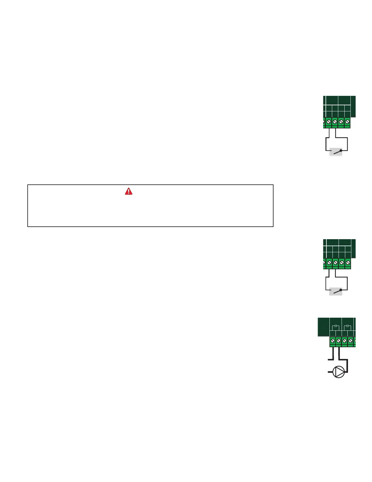
• Bring the two wires from the dry contact to the terminals marked SHUTDOWN/TSTAT/SETBACK- 31,32.
• The signal must be a dry contact only. No voltage can be placed across the SHUTDOWN/TSTAT/SETBACK
terminals.
(Terminals 29, 30)
• The Prove feature is provided to check system component operation and must be selected in the Startup Menu
from the Prove/DHW Sharing menu. See "Prove/Indirect Domestic Hot Water (DHW) Priority" on page 25.
• A typical use of this feature is to check for pump ow or combustion air damper status before ring any boiler.
• If the PROVE input is open on a call for heat, the TempTracker mod+ Hybrid will enable only the System Output.
All boiler outputs will be off when the PROVE input is open.
• A factory-installed jumper provides the System Prove signal. Do not remove the jumper unless it will be replaced
by a System Prove signal or these terminals are to be used for DHW call input.
• Bring the two wires from the dry contact to the terminals marked PROVE - 29, 30.
• Prove Input terminals can accept a dry-contact signal only. No voltage can be placed across these terminals.
The PROVE input cannot be used as a safety limit. All equipment must have its own
certied limit and safety controls as required by local codes. If Prove is selected in the
startup menu, no boiler stage will start unless Prove terminals are shorted. DO NOT
remove the PROVE jumper supplied unless replacing it with a Prove signal.
SYSTEM
A
B
C
D
1
2
RUNPROGRAM
DO NOT APPLY ANY VOLTAGE
TO INPUT TERMINALS
3
4
5
6
7
8
9
10
11
12
13
15
14
17
16
18
20
19
21
24
23
29
32
30
31
L
N
-
+
+
T
T
O
O
RS-485
mA
GND
VLT
SYS
A
B
C
D
PWR
CUR / VLT
A
-
+
+
mA
GND
VLT
-
+
+
mA
GND
VLT
+
+
mA
22
-
GND
VLT
+
mA
TEMP
OUTDOOR
O
O
TEMP
SYSTEM
EXTENSION
MODULE
CUR / VLT
B
CUR / VLT
C
CUR / VLT
D
PROVE
/DHW
SHUTDOWN
/SETBACK
FOR ALL CIRCUITS
120VAC, 6A RESISTIVE
OUTPUT RATINGS:
1A PILOT DUTY, 15A TOTAL
115VAC 60Hz , 30VA MAX
INPUT RATINGS:
USE COPPER WIRE,
CLASS 1 WIRE ONLY.
CAUTION
: RISK OF ELECTRIC SHOCK
More than one disconnect switch may be required
to de-energize the equipment before servicing.
ENCLOSED
ENERGY
MANAGEMENT
EQUIPMENT
99RA
/TSTAT
Prove Signal
(Terminals 29, 30)
• DHW can be used to raise system Set Point to the DHW Set Point as well as manage the System Pump according
to the DHW Priority setting. One of the DHW options must be selected from the Prove/DHW Sharing Startup
menu. See "Prove/Indirect Domestic Hot Water (DHW) Priority" on page 25.
• Wire an aquastat or a control to provide dry-contact closure on the DHW Call - 29, 30 terminals.
• Remove the jumper on the DHW terminals for proper operation.
• DHW Call terminals can accept dry contact signals only. No voltage can be placed across these terminals.
SYSTEM
A
B
C
D
1
2
RUNPROGRAM
DO NOT APPLY ANY VOLTAGE
TO INPUT TERMINALS
3
4
5
6
7
8
9
10
11
12
13
15
14
17
16
18
20
19
21
24
23
29
32
30
31
L
N
-
+
+
T
T
O
O
RS-485
mA
GND
VLT
SYS
A
B
C
D
PWR
CUR / VLT
A
-
+
+
mA
GND
VLT
-
+
+
mA
GND
VLT
+
+
mA
22
-
GND
VLT
+
mA
TEMP
OUTDOOR
O
O
TEMP
SYSTEM
EXTENSION
MODULE
CUR / VLT
B
CUR / VLT
C
CUR / VLT
D
PROVE
/DHW
/SETBACK
FOR ALL CIRCUITS
120VAC, 6A RESISTIVE
OUTPUT RATINGS:
1A PILOT DUTY, 15A TOTAL
115VAC 60Hz , 30VA MAX
INPUT RATINGS:
USE COPPER WIRE,
CLASS 1 WIRE ONLY.
CAUTION
: RISK OF ELECTRIC SHOCK
More than one disconnect switch may be required
to de-energize the equipment before servicing.
ENCLOSED
ENERGY
MANAGEMENT
EQUIPMENT
99RA
/TSTAT
Indirect
DHW Signal
(Terminals 3, 4)
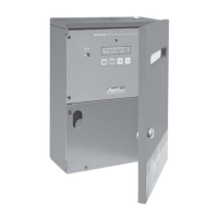
• The SYS output relay will energize and remain constantly energized whenever the outdoor temperature is below
the Outdoor Cutoff.
• When the outdoor temperature rises 2°F above the Outdoor Cutoff, the SYS output will remain energized for the
period set by the System Run-On then de-energize. See "System Run-On" on page 33.
• In addition, the System output will energize during summer DHW calls when DHW No Priority is selected. See
"Prove/Indirect Domestic Hot Water (DHW) Priority" on page 25.
• The SYS output has one Normally Open (N.O.) relay contact rated for (1/8 HP).
• The N.O. contacts are dry contacts only. They do not source any voltage.
• Class 1 voltages must enter the enclosure through a different opening from any Class 2 voltage wiring.
SYSTEM
A
B
C
D
1
2
RUNPROGRAM
DO NOT APPLY ANY VOLTAGE
TO INPUT TERMINALS
3
4
5
6
7
8
9
10
11
12
13
15
14
17
16
18
20
19
21
24
23
29
25
27
26
28
32
30
31
L
N
-
+
+
T
T
O
O
RS-485
mA
GND
VLT
SYS
A
B
C
D
PWR
CUR / VLT
A
-
+
+
mA
GND
VLT
-
+
+
mA
GND
VLT
+
+
mA
22
-
GND
VLT
+
mA
TEMP
OUTDOOR
O
O
TEMP
SYSTEM
EXTENSION
MODULE
CUR / VLT
B
CUR / VLT
C
CUR / VLT
D
PROVE
/DHW
SHUTDOWN
/SETBACK
FOR ALL CIRCUITS
120VAC, 6A RESISTIVE
OUTPUT RATINGS:
1A PILOT DUTY, 15A TOTAL
115VAC 60Hz , 30VA MAX
INPUT RATINGS:
USE COPPER WIRE,
CLASS 1 WIRE ONLY.
CAUTION
: RISK OF ELECTRIC SHOCK
More than one disconnect switch may be required
to de-energize the equipment before servicing.
ENCLOSED
ENERGY
MANAGEMENT
EQUIPMENT
99RA
/TSTAT
HYBRID
System Pump
or Pump Starter
L
N