16 Raypak, Inc.
HTC# 059105-00D
To set the Extension to a specic letter, remove the wiring cover and switch the Ext A/Ext B
to the desired letter. DO NOT set both extensions to the same letter to avoid errors.
F
H
J
Power
CAUTION:
Risk of Electric Shock.
More than one disconnect switch may be required
to de-energize the equipment before servicing.
PWR
L N
1 2
E
3 4
F
5 6
G
7 8
H
9 10
I
11 12
EXTENSION
MODULE
RS-485
Ext A
INPUT RATINGS:
115VAC 60Hz, 12VA MAX
Use Copper Conductors Only.
OUTPUT RATINGS:
120VAC, 6A RESISTIVE
1A PILOT DUTY, 15A TOTAL
FOR ALL CIRCUITS
E
G
I
Comm
Ext B
K
M
O
L
N
P
1514
VLTmA
CUR / VLT
181716
VLTmAGND
CUR / VLT
212019
VLTmAGND
CUR / VLT
242322
VLTmAGND
CUR / VLT
J
11 12
K M OL N P
E F G H
K ML N
13
GND
16
GND
19
GND
22
GND
2726
VLTmA
CUR / VLT
302916
VLTmAGND
CUR / VLT
25
GND
28
GND
I J
O P
ENCLOSED
ENERGY
MANAGEMENT
EQUIPMENT
99RA
120VAC Power
Six N.O. Boiler startup relay
outputs. Each is wired in series
with the boiler's limit circuit.
Six modulating outputs can be 4-20mA or voltage.
Go to TempTracker mod+ Hybrid Startup Menu to
determine the type of output for each stage.
LED indicates the
associated relay status.
Connect to any TempTracker mod+ or Hybrid
and additional Extension panels to add
additional stages using a RJ11 cable only
(cable provided with TempTracker mod+ Ext).
Extension Selection Switch to determine
Stage letters and LED colors.
Ext-A Stages E - J and all LEDs are Green
Ext-B Stages K - P and all LEDs are Red
This switch is covered with the Wiring Enclosure.
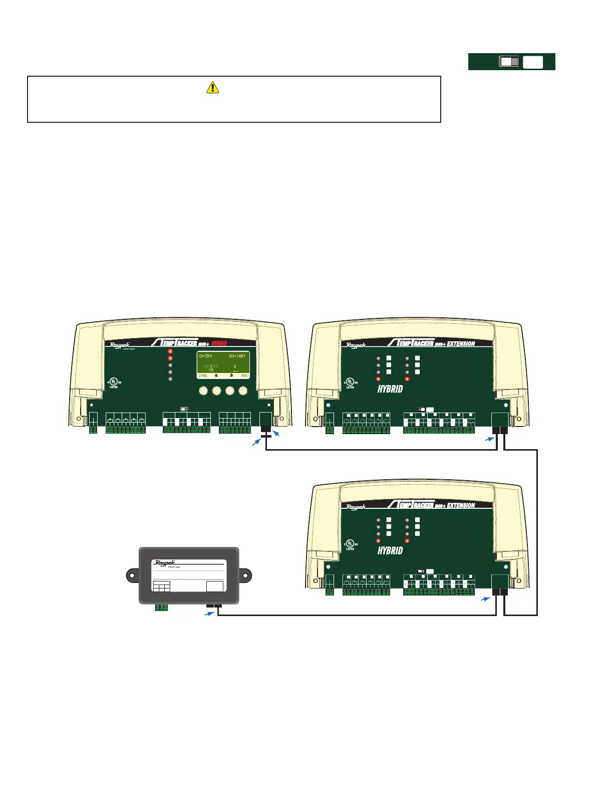
HYBRID
• The TempTracker mod+ Hybrid is equipped with a RJ45 socket and a RJ45 to RJ11 Adaptor to connect to extension
panels (#013179F) and 4-20mA EMS Interfaces (#012019). The Extension is equipped with two RJ11 sockets and a
RJ11 cable to connect to TempTracker mod+ Hybrid and an additional Extension. Use the RJ45 to RJ11 Adaptor on the
TempTracker mod+ Hybrid.
• The order in which the control, the extensions, and the interface are wired is not observed.
• Set each Extension to a different letter (EXT-A or EXT-B). The TempTracker mod+ Hybrid will assign the stage letters based on
the extension letter selected.
• Extension A will operate stages (E - J) and all the LEDs will be Green. However, Extension B will operate stages (K - P) and all
the LEDs will be Red. .
• Congure the Modulating and Sequencing Output Types after connecting the Extension panels to be able to congure their outputs.
See "Boiler Type" on page 20
• Only the 6-wire RJ11 cable supplied with the extension must be used for proper operation.
• RJ11 cables must be of a 6-wire with 6-pin terminals.
TempTracker mod+ Hybrid
connected to Two Extension Panels
and 4-20mA EMS Interface
TempTracker mod+ Extension ATempTracker mod+ Hybrid
TempTracker mod+ Extension B
Each Extension Panel or 4-20mA EMS
Interface comes with Connection Cable.
RJ11
RJ45
RJ45 to RJ11
Adaptor
RJ11
RJ11
4-20 mA EMS
4-20mA INPUT
+
Signal GND
1
2
3
RS485
EXTENSION
CONNECTORS
SYSTEM
A
B
C
D
1
2
RUNPROGRAM
DO NOT APPLY ANY VOLTAGE
TO INPUT TERMINALS
3
4
5
6
7
8
9
10
11
12
13
15
14
17
16
18
20
19
21
24
23
29
25
27
26
28
32
30
31
L
N
-
+
+
T
T
O
O
RS-485
mA
GND
VLT
SYS
A
B
C
D
PWR
CUR / VLT
A
-
+
+
mA
GND
VLT
-
+
+
mA
GND
VLT
+
+
mA
22
-
GND
VLT
+
mA
TEMP
OUTDOOR
O
O
TEMP
SYSTEM
EXTENSION
MODULE
CUR / VLT
B
CUR / VLT
C
CUR / VLT
D
PROVE
/DHW
SHUTDOWN
/SETBACK
FOR ALL CIRCUITS
120VAC, 6A RESISTIVE
OUTPUT RATINGS:
1A PILOT DUTY, 15A TOTAL
115VAC 60Hz , 30VA MAX
INPUT RATINGS:
USE COPPER WIRE,
CLASS 1 WIRE ONLY.
CAUTION
: RISK OF ELECTRIC SHOCK
More than one disconnect switch may be required
to de-energize the equipment before servicing.
ENCLOSED
ENERGY
MANAGEMENT
EQUIPMENT
99RA
/TSTAT
F
H
J
Power
CAUTION:
Risk of Electric Shock.
More than one disconnect switch may be required
to de-energize the equipment before servicing.
PWR
L N
1 2
E
3 4
F
5 6
G
7 8
H
9 10
I
11 12
EXTENSION
MODULE
RS-485
Ext A
INPUT RATINGS:
115VAC 60Hz, 12VA MAX
Use Copper Conductors Only.
OUTPUT RATINGS:
120VAC, 6A RESISTIVE
1A PILOT DUTY, 15A TOTAL
FOR ALL CIRCUITS
E
G
I
Comm
Ext B
K
M
O
L
N
P
1514
VLTmA
CUR / VLT
181716
VLTmAGND
CUR / VLT
212019
VLTmAGND
CUR / VLT
242322
VLTmAGND
CUR / VLT
J
11 12
K M OL N P
E F G H
K ML N
13
GND
16
GND
19
GND
22
GND
2726
VLTmA
CUR / VLT
302916
VLTmAGND
CUR / VLT
25
GND
28
GND
I J
O P
ENCLOSED
ENERGY
MANAGEMENT
EQUIPMENT
99RA
F
H
J
Power
CAUTION:
Risk of Electric Shock.
More than one disconnect switch may be required
to de-energize the equipment before servicing.
PWR
L N
1 2
E
3 4
F
5 6
G
7 8
H
9 10
I
11 12
EXTENSION
MODULE
RS-485
Ext A
INPUT RATINGS:
115VAC 60Hz, 12VA MAX
Use Copper Conductors Only.
OUTPUT RATINGS:
120VAC, 6A RESISTIVE
1A PILOT DUTY, 15A TOTAL
FOR ALL CIRCUITS
E
G
I
Comm
Ext B
K
M
O
L
N
P
1514
VLTmA
CUR / VLT
181716
VLTmAGND
CUR / VLT
212019
VLTmAGND
CUR / VLT
242322
VLTmAGND
CUR / VLT
J
11 12
K M OL N P
E F G H
K ML N
13
GND
16
GND
19
GND
22
GND
2726
VLTmA
CUR / VLT
302916
VLTmAGND
CUR / VLT
25
GND
28
GND
I J
O P
ENCLOSED
ENERGY
MANAGEMENT
EQUIPMENT
99RA