Regency
®
Model 4720 Control/Communicator Installation Manual (P/N 150476, Rev. A) Revised 10/98
25
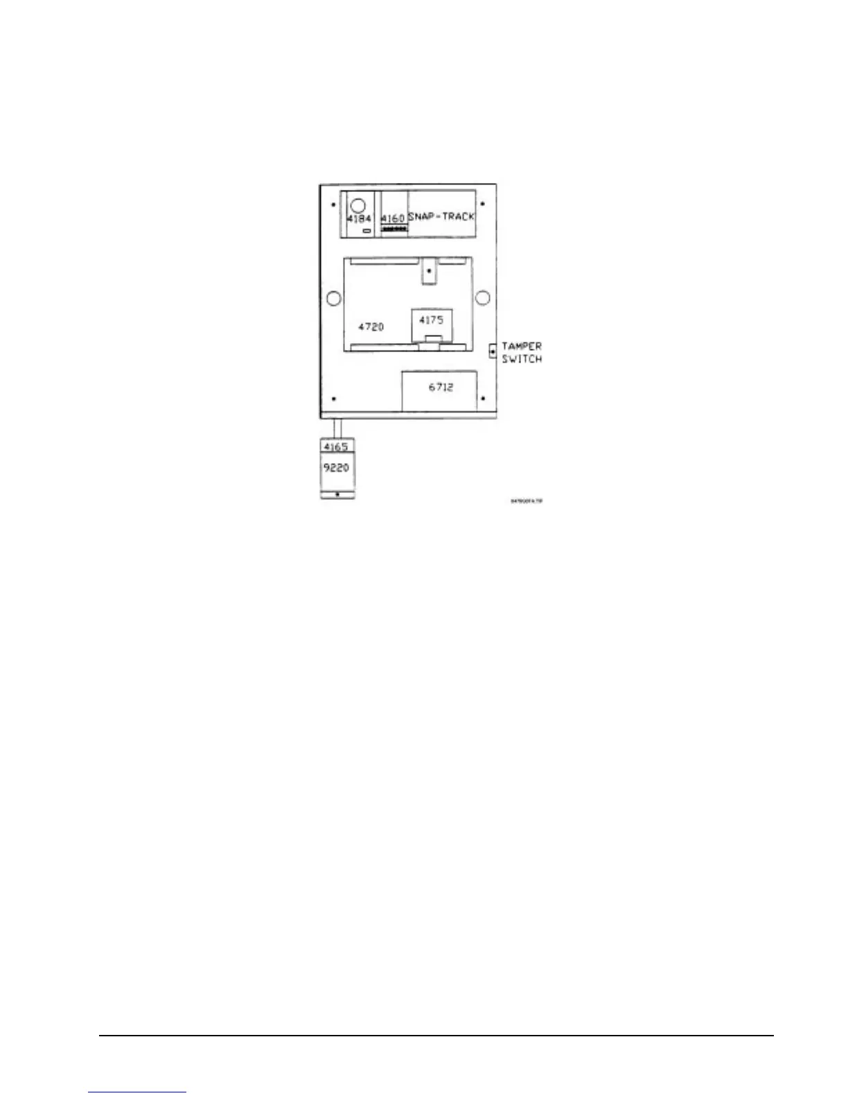
6.2 Mounting the Model 4720
Mount the Model 4720 so it is firmly secured to the wall surface. When mounting on concrete, especially
when moisture is expected, attach a piece of
3
/
4
-inch plywood to the concrete surface and then attach the
Model 4720 to the plywood. Mount all other desired components to the plywood interface.
Figure 6.2a: Suggested Mounting for the Control Panel
6.3 Installing the Model 9220 Power Transformer
An external transformer (Model 9220 included) is used to supply 16.5 V AC (40 VA) to power the system
under normal conditions and to supply charging current to the backup battery. The primary of this
transformer plugs directly into a conventional 115-V
AC
unswitched outlet. The secondary is wired into
Terminals 1 and 2 of the Model 4720 with a 2-conductor cable (preferably shielded). Use 18-gauge wire or
larger (i.e., AWG 16, 14, 12, etc.).
6.3.1 Model 4165 Transformer Housing
You must install the power transformer inside of the Model 4165 when installing the Model 4720 in
accordance with NFPA Standards.
1. Remove all power from the electrical outlet before attaching the Model 4165.
2. Remove the two (2) screws that hold the outlet to the single gang box.
3. using the two (2) screws that were removed, attach the Model 4165 box to the outlet and the
single gang box.
4. Plug the transformer into the outlet.
5. The secondary of the transformer must be run in conduit which may be attached to any of the
knockout holes.
6. Attach the housing cover to the housing plate using the two (2) screws provided.
Note: Electric door strikes and magnetic door holders are a potential source for damaging electrical
impulses. The auxiliary power from the Model 4720 should not be used for these devices. A
separate power source (such as Model 4195) should be used, and a reverse polarity diode should be
connected across the devices to suppress the impulses.