Regency
®
Model 4720 Control/Communicator Installation Manual (P/N 150476, Rev. A) Revised 10/98
27
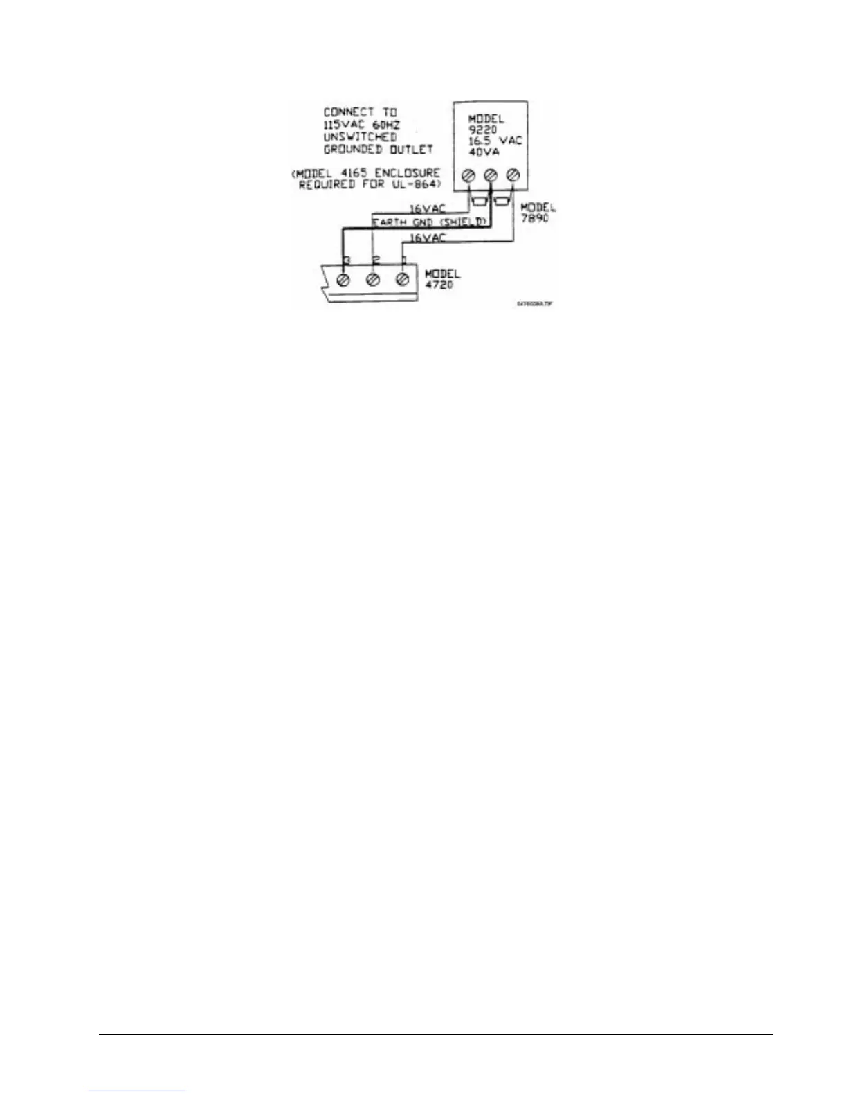
Figure 6.3.2a: Model 9220 Transformer Connection
6.4 Model 4195 Auxiliary Power Supply
The Model 4195 provides an additional 2.5 A of current for accessory items, 1.25 each at Terminals 3 and
4. The 4195 contains an AC power light that monitors the transformer. It also allows you to use two (2)
standby batteries to double the time that the system can function on battery standby. The 4195 also has
reverse battery indicators, and output overload indicators.
The 4195 should be mounted in the plastic board mount above the Model 4720. Figure 6.4a shows how to
wire the Model 4195. Connect the red battery lead from the Model 4720 to the spade lug labeled + on the
diagram below. Connect the black battery lead from the Model 4720 to the spade lug labeled “–” on Figure
6.4a below.
To enable the Model 4195 outputs to turn off for smoke detector reset, connect Terminal 6 of the Model
4195 to Terminal 10 of the Model 4720 instead of to Terminal 5 of the Model 4720.