Regency
®
Model 4720 Control/Communicator Installation Manual (P/N 150476, Rev. A) Revised 10/98
37
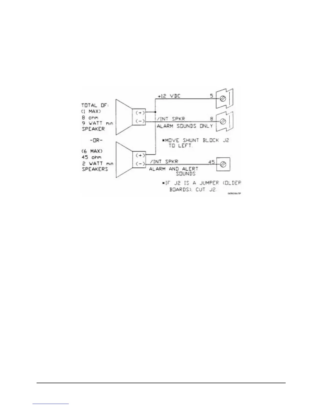
10.4 Internal Speaker Wiring
If an internal speaker is to be used such as in a touchpad, it must be connected between Terminal 5
(auxiliary power, speaker +) and Terminal 8 (speaker –). The 4720 was designed for use with an 8-Ω, 9-W
internal speaker or up to six 45-Ω, 1-W speakers.
If you wish to have alarm sounds only on some speakers, then cut Jumper J2 (move shunt block to the left/
“out” position). After doing so, speakers connected to Terminal 8 will produce alarm sounds only, but
speakers connected to Terminal 45 will still produce both alarm and alert sounds.
Figure 10.4a: Internal Speaker Wiring
10.5 Model 4180 Status Relays
See the Model 4180 Status Display Module Wiring Instructions (P/N 150445) for information on how to
install the Model 4180. Be sure to maintain a physical separation of at least one half inch between the field
wires and the Model 4180 connection points. This will prevent transient damage to the Model 4180
connection points.