18
Regency
®
Model 4720 Control/Communicator Installation Manual (P/N 150476, Rev. A) Revised 10/98
4 4720 Control Panel Overview
4.1 Current Draw Calculations
4.1.1 Total Standby and Alarm Current Draw
Table 4.1.1.0a is a worksheet to help you calculate the amount of current the system draws on
standby and in an alarm condition, to make sure the installation does not exceed power supply and
calculating current draw for battery capacity. The second column shows the LED that indicates
excessive current draw for each accessory, for PC board Revision L and later revisions. The third
column shows the fuse through which each accessory draws power, for earlier PC board revisions.
The remaining columns are explained in the instructions below.
To use the worksheet in Table 4.1.1.0a:
1. Look down through the Device column to identify which devices are and are not included in this
installation.
a. Cross out any device that is not used, extending the line all the way across the page.
b. In the spaces provided, write in any other devices not printed on the sheet.
c. For each device, list the number of devices being used in the # of devices column. The
maximum number of devices is shown in parentheses ( ).
2. Go through the Current per device column and fill in any missing current ratings for the devices
used. Note that some devices have different ratings for standby and alarm condition. For devices
not mentioned in the manual, refer to the device manual for the current ratings.
3. For each device, multiply the # of devices times the Current per device, and enter the total in
either the Total standby current or Total alarm current column, whichever is appropriate. For
devices with different standby and alarm currents, be sure to do the calculation for each rating.
Do NOT write in the shaded areas.
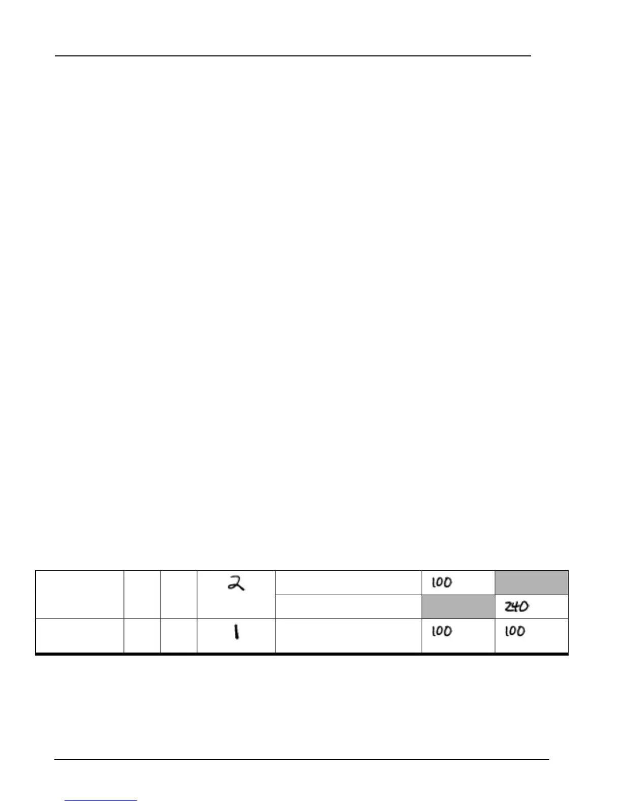
Example: Suppose your installation included two (2) LCD Touchpads, a 4115 Zone Expander, and no 4110
Zone Expander. After you had worked this far in the procedure, part of your worksheet would
appear as shown below:
(This is NOT the worksheet. It is an
EXAMPLE, to show you how to
complete the worksheet. The
worksheet begins on the next page.)
. . .
4660B/C/R LCD
Touchpad
2F2
(15 max. - not UL)
×
Standby: 50 mA =
mA
×
Alarm: 120 mA =
mA
4115 Zone
Expander
3F3
(2 max.)
×
100 mA =
mA mA
. . .