Regency
®
Model 4720 Control/Communicator Installation Manual (P/N 150476, Rev. A) Revised 10/98
19
4. Add up each of the two To t a l columns and write the totals in the spaces on the last line (4th page)
of the worksheet. When you add the columns, remember to:
• Include the values from ALL three (3) pages of the worksheet (Table 4.1.1.0a).
• Include both printed and handwritten values.
5. For UL installations—To obtain 24-hour standby battery power, the Total standby current draw
must not exceed 200 mA when using the Model 4720 only, and must not exceed 350 mA when
one 4195 is used.
6. Calculate the Alarm current draw on the protective devices indicated by LEDs 2 and 3 (F2 and
F3 in PC board revisions prior to Revision L), following the directions in Section 4.1.2. The total
combined Alarm current draw on these protective devices must not exceed 1300 mA. To obtain
more active current, touchpads can be powered by the Model 4195, which provides an additional
2500 mA.
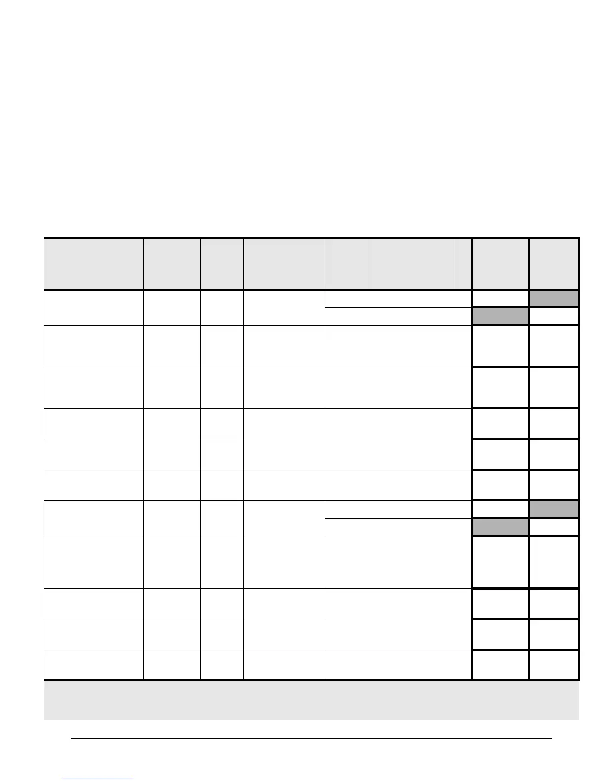
Table 4.1.1.0a: Current Load Worksheet
Device LED
(Revision
L
& Later)
Fuse #
(Prev.
Revs.)
# of Devices
(Max. Allowed)
Times Current Per
Device
*2
= Total
Standby
Current
Total
Alarm
Current
4720*
11× Standby: 95 mA = 95 mA
× Alarm: 130 mA = 130 mA
4203 SlimLine
Weather Resis-
tant Touchpad*
1
(4 max.—not UL)*
2
× 10 mA = mA mA
4205 SlimLine
Access Control
Touchpad
2F2
15 max.—not UL)
× 10 mA = mA mA
4300 Swipe Card
Reader
2F2
(15 max.—not UL)
× 25 mA = mA mA
4310, 4312 Proxim-
ity Card Readers
2F2
(15 max.—not UL)
× 130 mA = mA mA
4420 Card Reader
Interface
2F2
(15 max.—not UL)
× 20 mA = mA mA
4660B/C/R LCD
Touchpads
2 F2 15 (or 5 for 24-hour
standby)
× Standby: 52 mA = mA
× Alarm: 112 mA = mA
4110 Zone
Expander
(replaced by
4115)
3F3
(2 max.)
× 105 mA = mA mA
4115 Zone
Expander
3F3
(2 max.)
× 100 mA = mA mA
4125 Zone
Expander
3F3
(2 max.)
× 30 mA = mA mA
4130 Zone
Expander
3F3
92 max.—not UL)
× 100 mA = mA mA
* Note 1: If no LED or fuse is shown, the accessory is resistively current limited.
* Note 2: Not UL = Not investigated by UL.
* Note 4: Not Ul = The maximum number shown for smoke detectors is for the entire installation (NOT per zone).