20
Regency
®
Model 4720 Control/Communicator Installation Manual (P/N 150476, Rev. A) Revised 10/98
4140 Intercom/Tele-
phone Controller
2F2
(1 max.)
× 100 mA = mA mA
4150 Auxiliary Con-
trol Module
3F3
(1 max.)
× Standby: 100 mA = mA
× Alarm: 70 mA = mA
4640 Intercom Sta-
tion
3F3
(8 max.)
× 8 mA = mA mA
4724 Control
Expander
——
(1 max.)
× Standby: 40 mA = mA
× Alarm: 40 mA = mA
5260 Printer Inter-
face
3F3
(1 max.)
× 25 mA = mA mA
7369 Two-Way
Audio Listen-in
Module
2F2
(1 max.—not UL)
× 100 mA = mA mA
5520 Desktop Pro-
grammer
1 × 30 mA = 30 mA 30 mA
Smoke detectors
ESL 445AT
5F3
(7 max.) × 4
× Standby: 1.5 mA = mA
× Alarm: 70 mA = mA
ESL 445C, 445CT,
445CR, 445CRT
5F3
(12 max.)
× Alarm: 40 mA = — mA
Detection Systems
DS200-4W,
DS200HD-4W
5F3
(12 max.)
× Standby: .08 mA = mA
× Alarm: 25 mA = mA
Hochiki America,
Corp. SLK-12
5F3
(10 max.)
× Standby: .055 mA = mA
× Alarm: 10 mA = mA
Gentex 8120,
8120T, 8120P,
8120PT, 8120PH
5F3
(7 max.)
× Standby: 5 mA = mA
× Alarm: 60 mA = mA
ESL 204A Power
Supervision Unit
(One required for
each smoke
detector loop)
5F3 — × 40 mA = 40 mA 40 mA
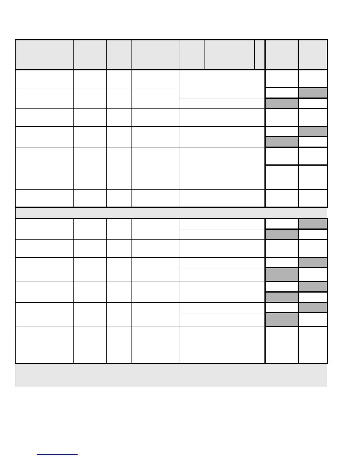
Table 4.1.1.0a: Current Load Worksheet
Device LED
(Revision
L
& Later)
Fuse #
(Prev.
Revs.)
# of Devices
(Max. Allowed)
Times Current Per
Device
*2
= Total
Standby
Current
Total
Alarm
Current
* Note 1: If no LED or fuse is shown, the accessory is resistively current limited.
* Note 2: Not UL = Not investigated by UL.
* Note 4: Not Ul = The maximum number shown for smoke detectors is for the entire installation (NOT per zone).