Regency
®
Model 4720 Control/Communicator Installation Manual (P/N 150476, Rev. A) Revised 10/98
21
4.1.2 Current Draw on Protective Devices Indicated by LEDs 2 and 3 (F2 and F3)
Calculate the alarm current drain on the protective devices indicated by LED 2 (F2) and LED 3 (F3).
First complete the calculations in Table 4.1.1.0a on the previous pages. Then use Table 4.1.2a to
perform the following calculations:
1. Write the Total alarm current (from Table 4.1.1.0a) in Column 3.
2. If there are any additional devices that are not associated with LED 2 or LED 3 (F2 or F3), write
them in the space provided, and write their current draws in Column 2.
3. Add Column 2. Write the total in Column 3 on the line labeled Alarm current NOT associated
with LED 2 or 3 (F2 or F3).
Model 7181 Univer-
sal Zone Con-
verter
5 F3 (1 per zone max.)
(See the Model 7
181 Installa-
tion Manual
—P/N 150632,
in the electrical specifica-
tions section—for current
draw information. Be sure to
take the appropriate infor-
mation for the configuration
in which you’ve wired the
Model 7181.)
Wheelock Bell
2F2
3 max.)
× Standby: 0 mA = 0 mA
× Alarm: 125 mA = mA
8-ohm Speaker
2F2
(1 max.)
× Standby: 0 mA = mA
× Alarm: 750 mA = mA
45-ohm Speaker
2F2
(6 max.)
× Standby: 0 mA = mA
× Alarm: 133 mA = mA
Siren (15-watt
speaker)
1F1
(1 max.
× Standby: 0 mA = mA
× Alarm: 133 mA = mA
Zone Input
—
(16 max.)
× Standby: 0.6 mA = mA
Additional devices not listed above
× Standby: ____ mA = mA
× Alarm: ____ mA = mA
× Standby: ____ mA = mA
× Alarm: ____ mA = mA
× Standby: ____ mA = mA
× Alarm: ____ mA = mA
Total current ratings of all devices in system
mA
Standby
mA
Alarm
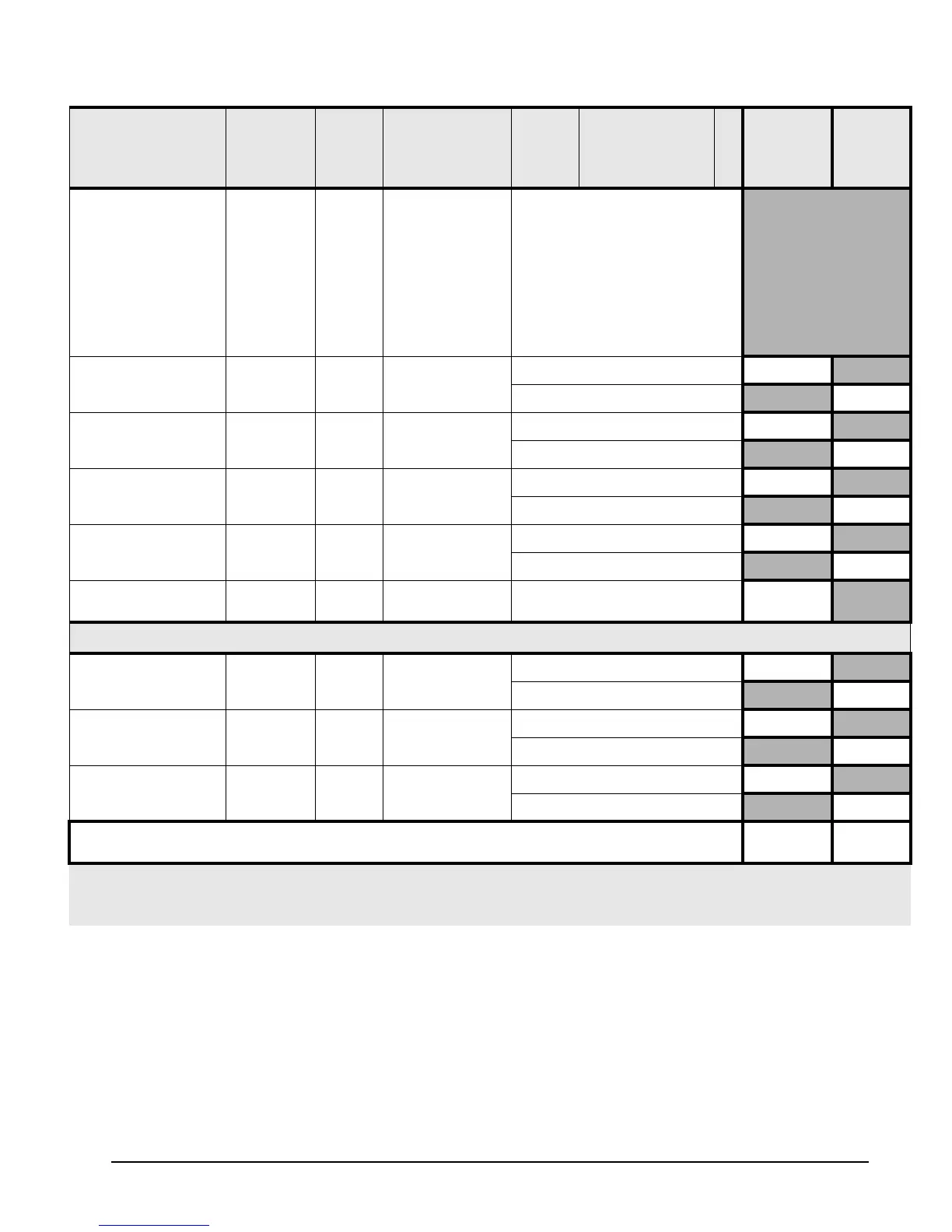
Table 4.1.1.0a: Current Load Worksheet
Device LED
(Revision
L
& Later)
Fuse #
(Prev.
Revs.)
# of Devices
(Max. Allowed)
Times Current Per
Device
*2
= Total
Standby
Current
Total
Alarm
Current
* Note 1: If no LED or fuse is shown, the accessory is resistively current limited.
* Note 2: Not UL = Not investigated by UL.
* Note 4: Not Ul = The maximum number shown for smoke detectors is for the entire installation (NOT per zone).